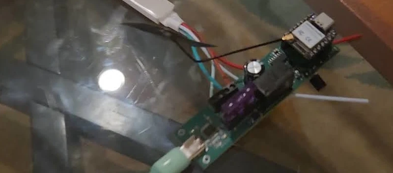
The Adafruit Funhouse is a ESP32-S2 based board from Adafruit. The board was once part of their AdaBox mystery project subscription service at one point which is how I came to acquire it.
In terms of features on the board itself:
- There is a header for a PIR sensor
- 5 RGB DotStar LEDs
- A TFT display
- Buzzer speaker
- Light sensor
- Humidity, temperature, and pressure sensors
- Three physical buttons
- Three touch pads and a touch slider
- An on/off switch
- An i2c port (STEMMA QT / JST SH 1mm)
- 3 JST ports for additional connections
Which makes for a really nice Home monitoring device. Adafruit built their own firmware and provides several examples for getting up and running with the device. Given this is an ESP32 based device though I figured I could easily get it on my Home Assistant Yellow install by putting together a configuration which covered the capabilities of the device.
To simplify the process I looked over GitHub for any existing configurations that anyone may have uploaded for the board. I figured I could then modify further as I need.
In doing so I ran into the following configuration from the user kbx81.
The configuration here is great but it has a lot of additional data related to some local energy service the user has access to.
You can visit my gist to see my changes but the primary changes were to switch to Eastern US time, to remove the energy data related logic, and to add some basic graphs for the onboard sensors. I’ll go into detail related to some elements of how this configuration works below so you can understand it better.

Note: The touchpads also sometimes act a bit weird I’ve found triggering other random buttons on the Home Assistant side.
esphome:
  name: funhouse
  friendly_name: Funhouse
  platformio_options:
    board_build.mcu: esp32s2
    board_build.variant: esp32s2
This section configures ESPHome (and platformio) for the board type.
esp32:
  board: adafruit_funhouse_esp32s2
  framework:
    type: esp-idf
    version: 5.0.2
    platform_version: 6.3.2
The framework is selected here along with the version. We’re using the esp-idf framework here but we could attempt to use the Arduino framework instead.
esp32:
  board: adafruit_funhouse_esp32s2
  framework:
    type: arduino
    version: 2.0.9
    platform_version: 5.4.0
Following this, as you can see by following along in the gist, the psram, touch buttons, logger, ota, and wifi are also configured.
time:
  - platform: homeassistant
    id: esptime
    timezone: EST+5EDT,M3.2.0/2,M11.1.0/2
Next the timezone is specified. If you’re in a different timezone than me you’ll want to update this.
To format the timezone you can use the information provided here.
The important parts TLDR:
For example, here is how we would specify Eastern Standard Time, but without any Daylight Saving Time alternative:
EST+5
The second format is used when there is Daylight Saving Time:
std offset dst [offset],start[/time],end[/time] The initial std and offset specify the standard time zone, as described above. The dst string and offset are the abbreviation and offset for the corresponding Daylight Saving Time zone; if the offset is omitted, it defaults to one hour ahead of standard time.
The remainder of the specification describes when Daylight Saving Time is in effect. The start field is when Daylight Saving Time goes into effect and the end field is when the change is made back to standard time.
i2c:
  id: i2c_bus
  frequency: 400kHz
  scl: 33
  sda: 34
  scan: false
Connects to the i2c bus with a frequency of 400KHz on SCL GPIO 33 and SDA GPIO 34.
spi:
  - id: spi_lcd
    clk_pin: 36
    mosi_pin: 35
  - id: spi_led
    clk_pin: 15
    mosi_pin: 14
Further here has SPI support for both LED control of the DotStar RGB LEDs and of the LCD screen. In addition there is a separate backlight LED that must be driven high for the screen contents to be visible.
If you check the light section further on in the document (skipping ahead here) you can see this defined there:
light:
  - platform: monochromatic
    id: lcd_backlight
    name: Display Backlight
    output: lcd_backlight_pwm
    restore_mode: RESTORE_DEFAULT_ON
  - platform: spi_led_strip
    id: dotstar_light
    spi_id: spi_led
    data_rate: 40MHz
    name: APA102 LEDs
    restore_mode: RESTORE_DEFAULT_OFF
    num_leds: 5
    effects:
      - addressable_flicker:
      - addressable_color_wipe:
      - addressable_rainbow:
      - addressable_scan:
      - addressable_twinkle:
      - addressable_random_twinkle:
      - addressable_fireworks:
output:
  - platform: ledc
    id: lcd_backlight_pwm
    pin: 21
    channel: 0
Where the LED backlight is enabled here for use. In addition several LED effects are configured for the DotStar LED strip. Honestly I think WLED looks a lot better than the ESPHome effects as so far only rainbow has really impressed me for these.
font:
  - file: "fonts/Roboto-Regular.ttf"
    id: roboto_large
    size: 64
  - file: "fonts/Roboto-Regular.ttf"
    id: roboto_med
    size: 28
  - file: "fonts/Roboto-Regular.ttf"
    id: roboto_metric
    size: 22
  - file: "fonts/Roboto-Regular.ttf"
    id: roboto_small
    size: 12
I configured several font sizes for use with the screen. For the font type I used Roboto which is licensed under the Apache License, Version 2.0.
Most of the other configuration is fairly straightforward but highlighting a few of them for the purposes of this post.
  - platform: gpio
    id: motion_sense
    name: Motion Detection
    device_class: motion
    pin:
      number: 16
The motion sensor output.
  - platform: gpio
    id: button_input_0
    name: Button Up
    pin:
      number: 5
  - platform: gpio
    id: button_input_1
    name: Button Select
    pin:
      number: 4
    on_press:
      - display.page.show: page1
  - platform: gpio
    id: button_input_2
    name: Button Down
    pin:
      number: 3
    on_press:
      - display.page.show: page2
  - platform: gpio
    id: button_input_back
    name: Button 0
    pin:
      number: 0
      inverted: true
      mode:
        input: true
        pullup: true
    on_press:
      - light.toggle: dotstar_light
  - platform: esp32_touch
    id: touchpad_left
    name: Touchpad Left
    pin: 6
    threshold: 50000
    on_press:
      - rtttl.play: "alert 1:d=8,o=5,b=160:e"
    on_release:
      - rtttl.play: "alert 1:d=8,o=4,b=160:a"
Buttons and touchpad configurations with some sound outputs via rtttl.play.
color:
  - id: color_heavy_blue
    red: 39.2%
    green: 58.4%
    blue: 92.9%
  - id: color_cool_purple
    red: 50.2%
    green: 0%
    blue: 50.2%
  - id: color_sea_green
    red: 18.0%
    green: 54.5%
    blue: 34.1%
  - id: color_red
    red: 100%
    green: 0%
    blue: 0%
  - id: color_yellow
    red: 100%
    green: 100%
    blue: 0%
  - id: color_green
    red: 0%
    green: 100%
    blue: 0%
  - id: color_blue
    red: 0%
    green: 0%
    blue: 100%
  - id: color_gray
    red: 60%
    green: 60%
    blue: 60%
  - id: color_white
    red: 100%
    green: 100%
    blue: 100%
  - id: elec_cost_color
    red: 100%
    green: 0%
    blue: 100%
Color configuration for use with the LCD screen further below (like the fonts before).
output:
  - platform: ledc
    id: rtttl_out
    pin: 42
    channel: 2
rtttl:
  output: rtttl_out
  on_finished_playback:
    - logger.log: 'Song ended!'
The buzzer is setup for output here and rttl configured.
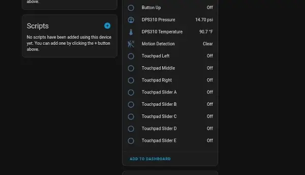
Phototransistor ADC sensor…can’t use with Wi-Fi :(
As mentioned in the original file I referenced and carried over here the Phototransistor ADC sensor unfortunately can’t be used when Wi-Fi is enabled. As I’ll be using ESPHome to constantly stay connected it makes it useless for this configuration unfortunately.
The other sensors, however, can be configured:
sensor:
  - platform: aht10
    temperature:
      id: aht20_temperature
      name: AHT20 Temperature
      filters:
        - offset: -2.0
    humidity:
      id: aht20_humidity
      name: AHT20 Humidity
    update_interval: 15s
  - platform: dps310
    temperature:
      id: dps310_temperature
      name: DPS310 Temperature
      filters:
        - offset: -2.6
    pressure:
      id: dps310_pressure
      name: DPS310 Pressure
    update_interval: 15s
Given we setup the i2c bus previously these are able to connect given the sensors have been setup to work with ESPHome via the configuration defaults.
graph:
  - id: temperature_graph
    sensor: aht20_temperature
    duration: 1h
    border: False
    color: color_heavy_blue
    width: 150
    height: 50
  - id: pressure_graph
    sensor: dps310_pressure
    duration: 1h
    border: False
    color: color_cool_purple
    width: 150
    height: 50
  - id: humidity_graph
    sensor: aht20_humidity
    duration: 1h
    border: False
    color: color_sea_green
    width: 150
    height: 50
Here I configure the graphs I used for the output.
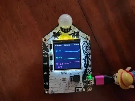
display:
  - platform: st7789v
    id: main_lcd
    spi_id: spi_lcd
    model: Adafruit Funhouse 240x240
    rotation: 180
    data_rate: 80MHz
    update_interval: 1s
    pages:
      - id: page1
        lambda: |-
          const uint8_t header_height = 20;
          const uint8_t vert_spacing_offset = 45;
          const uint8_t vert_center = ((it.get_height() - header_height) / 2) + header_height;
          auto logo_color = id(conn_status).state ? id(color_gray) : id(color_red);
          it.strftime(6, 6, id(roboto_small), id(color_gray), TextAlign::TOP_LEFT, "%Y-%m-%d", id(esptime).now());
          it.strftime((it.get_width() - 6), 6, id(roboto_small), id(color_gray), TextAlign::TOP_RIGHT, "%H:%M:%S", id(esptime).now());
          it.print(it.get_width() / 2, 6, id(roboto_small), logo_color, TextAlign::TOP_CENTER, "ESPHome");
          it.graph(90, 40, id(temperature_graph));
          it.graph(90, 100, id(humidity_graph));
          it.graph(90, 160, id(pressure_graph));
          it.printf(40, 70, id(roboto_metric), id(color_heavy_blue), TextAlign::CENTER, "%.1f°", id(aht20_temperature).state * 1.8 + 32);
          it.printf(40, 130, id(roboto_metric), id(color_sea_green), TextAlign::CENTER, "%.1f%%", id(aht20_humidity).state);
          it.printf(40, 190, id(roboto_metric), id(color_cool_purple), TextAlign::CENTER, "%.1f", id(dps310_pressure).state);
          it.printf(40, 220, id(roboto_metric), id(color_cool_purple), TextAlign::CENTER, "nhPa");
Finally the display here is configured and I’ve included the first page above for reference. It connects to the LCD SPI that was previously setup and it displays the data on the screen according to what has been configured.
I kept page 2 in place with the data from the original setup both so that I’d have the existing page switching logic configured as I further update this. I’m planning on getting some additional sensors down the line I’ll connect via the JST 3 pin interface and will use the subsequent page at that point.
Was a neat project as it didn’t take me too long to do and it finally put my Adafruit Funhouse to good use. I’m planning on doing the same to my Adafruit MagTag next as I have little use for it currently.