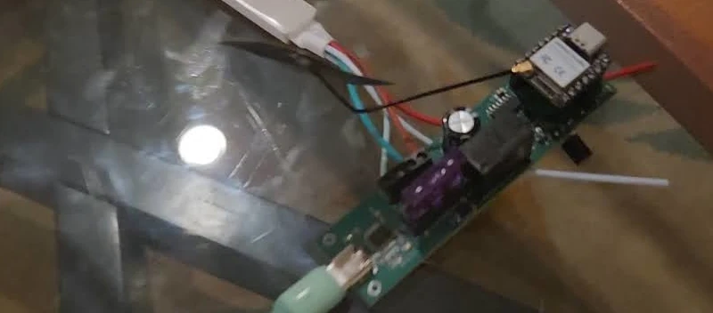
For this project I’ve modified a pcsensor FS2020U1 USB Foot Switch Control device from aliexpress a bit back (from a different seller) to work with my microcontroller for use in various projects.
Printables link: https://www.printables.com/model/941756-foot-pedal-adapter
Additional Project items (affiliate links):
Background
Awhile back I purchased this foot pedal from Aliexpress as a way to add an additional control device to my set of random devices. A big driving factor was that I know it’ll make for a great component to use with future videos so I wanted to do the legwork to get this piece in place ahead of a need.
Initial investigations
I removed the screws from the device’s bottom and began investigating the layout of the circuit board. Upon opening it was clear the circuit is a simple IR emitter and receiver (versus a mechanical switch). The mechanism for signaling in this case was to break that emitter’s line of sight to the receiver with a piece of plastic that falls into the cutout between them as the spring is compressed down by a foot.
My initial investigations of the board left me fairly puzzled. I could see each of the boards was the same. I could also see the power lines were connected.
Initially I was going to use the existing wires coming from the board but realized it powered the sensor by doing a round-robin power setup powering one signal pin at a time while checking the state of the others (using a reverse biased diode to power the board from the main board). This worked well during my testing (setting one pin as power and checking the state of the pedals) but wasn’t feasible for the microcontroller to source that much current from the signal pins. This falstad circuit shows power from the left signal wire, from the middle signal wire and from the right signal wire illustrates a similar circuit setup as the one used by the controller with the 4 wire approach. One of the pins as a power source with the other two acting as an open collector. This approach does work as shown above but it could present a problem for a microcontroller without additional components as the pins wouldn’t be able to source enough current without use of a mosfet for each signal line (albeit one could just use two pins for power).
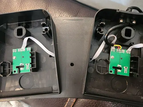
Luckily, the main board still surfaced the power pin though (each of the side boards is a duplicate of the main) so I realized I could easily replace the wire with a 5 wire one I grabbed from Amazon and be able to use this with my projects going forward.
Wire strain relief component
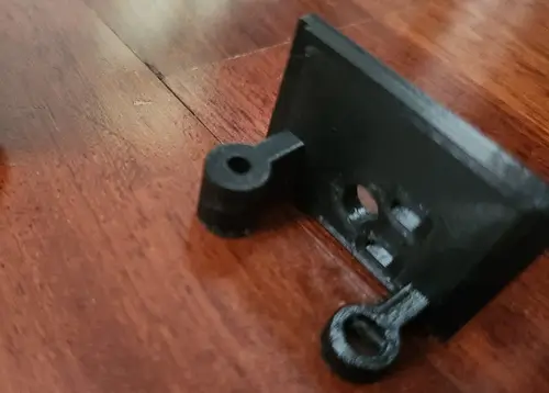
The original setup used an injection molded piece around the 4 wire cable. This helped to provide strain relief for the wire keeping it from being dislodged from the circuit board. This also unfortunately meant the existing piece would need to be replaced completely. I measured the existing part, adjusted the design slightly, and printed a component.
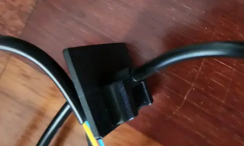
My original design actually didn’t work here but involved using a PG-7 cable gland for preventing cable movement. The problem related to the top component of the foot pedal as it has a plastic piece which comes rather low. The PG-7, even at the bottom of the replacement piece, just was too high in the piece with its backing nut so it couldn’t be inserted without modifying the pedal shell which I did not want to do here.
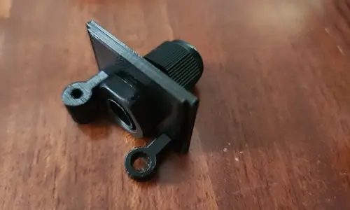
As a result I designed a replacement piece that was much simpler and only had the wire going through versus any additional hardware. To aid with wire strain I added holes for a zip tie which can be used to keep the wire from moving.
Wire attachment
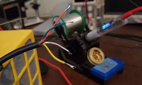
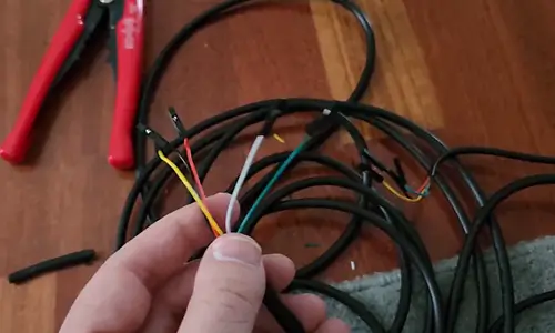
I tinned and soldered the wires to the main board, used a zip tie, and crimped the stripped wires on the other end of the board for use with a dupont connector.
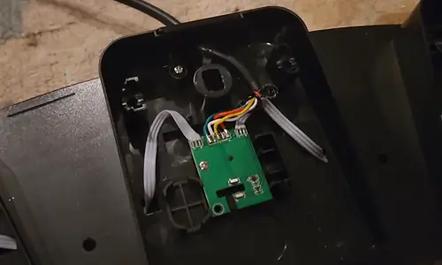
At this point the device is ready for use with a microcontroller.
Microcontroller use
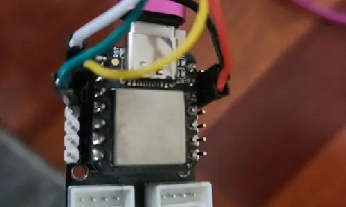
Now with the 5 wires soldered and with dupont connectors on the other side it’s easy to get running with a sketch. I connected the red wire to 3V3, black to GND, and used D0-D2 as signal wires.
The code for the logic used in my example is rather simple as well:
#include "Keyboard.h"

const int leftPin = D0;
const int middlePin = D1;
const int rightPin = D2;

void setup() {
  Serial.begin(9600);

  pinMode(leftPin, INPUT_PULLUP);
  pinMode(middlePin, INPUT_PULLUP);
  pinMode(rightPin, INPUT_PULLUP);
}

void loop() {
  if (digitalRead(leftPin) == LOW) {
    Keyboard.press('a');
  } else {
    Keyboard.release('a');
  }

  if (digitalRead(middlePin) == LOW) {
    Keyboard.press('w');
  } else {
    Keyboard.release('w');
  }

  if ( digitalRead(rightPin) == LOW) {
    Keyboard.press('d');
  } else {
    Keyboard.release('d');
  }

  delay(100);
}
The pins are set to inputs with a pullup. The loop logic simply checks if the pins are reading LOW indicating that the pedal has been pressed down causing the blocker to interfere with the emitter / receiver setup. Once brought LOW the logic emulates the pressing of the awd keys (used with awsd control schemes to move forward and turn or strafe).
Testing

With the circuit in place I opted to test the functionality with the game Rebel Galaxy. In this game the a and d correspond with turning while the w is used for the booster throttle.
Concluding thoughts
This was a neat project that puzzled me for a bit. I definitely felt accomplished figuring out the unique round robin power used here with the initial circuit.
I’d like to design my own foot pedal in the future using a mechanical switch instead of the line break used here. Not sure if I’d reuse the enclosure here or 3D print my own but worth a revisit some day. For now this seems great and I’ll be using this for some projects I have planned.

