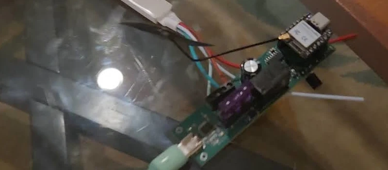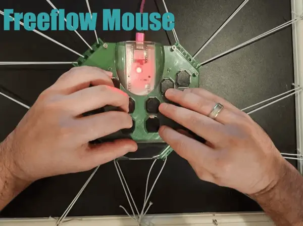
For this project I’m utilizing my DFRobot Unihiker (affiliate link) to control my Adeept 4WD Omni-directional Mecanum Wheels Robotic Car Kit for ESP32-S3.
The associated code for this project can be found here.
Prerequisites
For more information about the robot car kit you can check my article on the lessons from the Adeept tutorials with the car.
Background
There’s an ongoing contest from DFRobot around utilizing the Unihiker for various project types. I have a Unihiker and have used it for multiple (1, 2) projects previously. The Unihiker device is fairly easy to work with: there are various example projects, the pingpong libraries makes interfacing with various sensors a simple task, and it has a large screen and touchscreen.
Setup
Banana Pi PicoW S3 CircuitPython
The first step is to get your Banana Pi PicoW S3 setup to have the CircuitPython code. The majority of the libraries used for this project come as part of the omnidirectional car kit’s logic but a CircuitPython bundled library is needed as well.
If you reference the code only the code.py file from the repository will be used for car. Depending upon the version of CircuitPython you used you may need either the 8.x or 9.x bundle. I used the 9.x bundle as I flashed that version of CircuitPython to the board.
- Copy
adafruit_ht16k33to the drive’s lib folder - From Adeept’s code bundle for the car copy over the
avoid_obstacles.pyandBPI_PicoW_S3_Car.py. I placed them at the root folder of the project - Finally copy the
code.pyfrom the repository above to the drive
With those in place the setup process for the car is complete and we can move onto the Unihiker setup.
Code Breakdown
I’m going to go into the code I added / adjusted here. So I took the original car control logic and modified it for commands I wanted to handle. I won’t go into every part so you should reference the code in the repository for actually copying it over but this may prove helpful if you want to understand the different elements of it.
# Connect WIFI
ssid, pw = ('BPI-PicoW-S3', '12345678')

wifi.radio.start_ap(ssid=ssid, password=pw)
time.sleep(1)
print(f'WiFi AP mode Started! SSID is {ssid}, IP={wifi.radio.ipv4_address_ap}')
So this logic sets up an access point. This access point can be connected to from the Unihiker to then control the car. Having it act as an access point (vs connecting to an existing network) allows one to take the car anywhere. I found the car to use the address 192.168.4.1 for the access point it created (I used CircuitPython serial to read the output).
servo = Servo()
servo.set_angle(board.GP7,0)
I noticed during initialization for the servo head moves which can cause it to not point forward when the car begins movement. In order to address this I set the angle of the servo to 0 after initialization. In this way when the obstacle avoidance logic is running the car is always reading the forward direction. You’ll notice this is using the pinout from the motor shield / banana pi PicoW S3 as it’s using CircuitPython. If you were using arduino you’d need to use the ESP32S3 related GPIO numbers but in this case it’s straightforward given that mapping.
with pool.socket(pool.AF_INET, pool.SOCK_STREAM) as server_socket:
    server_socket.bind(('0.0.0.0', 8080))
    server_socket.listen(5)

    while True:
        server_socket.settimeout(0.1)
        try:
            connection, address = server_socket.accept()
            print("Connected by", address)
            connections.append(connection)
        except OSError:
            pass
The logic then creates a socket and once connected proceeds.
for connection in list(connections):
  buf = bytearray(BUFF_SIZE)
  try:
      size = connection.recv_into(buf)
  except OSError as e:
      if e.errno == errno.EAGAIN:
          continue
      else:
          raise

  if not size:
      connection.close()
      connections.remove(connection)
      break

  data = buf[:size].decode()
  print("Received data:", repr(data))
Then for each connection it confirms if the connection has been closed and if so removes it else it decodes and processes the data.
Given the data in this case is just a command the logic is pretty simple from here out.
if data == "obstacle_avoidance":
  try:
      avoid_obstacles_mark = 0
      while True:
          avoid_obstacles.test()

          buf = bytearray(BUFF_SIZE)
          try:
              size = connection.recv_into(buf)
          except OSError as e:
              if e.errno == errno.EAGAIN:
                  continue
              else:
                  raise

          if not size:
              break

          data = buf[:size].decode()
          print("Received data:", repr(data))
  except KeyboardInterrupt:
      motor.motor_stop()
else:
I persisted the existing obstacle avoidance code here. It triggers the logic in that associated library provided by Adeept which prevents the car from running into obstacles by using its sensor to detect range.
  direction_commands = [
      "forward",
      "backward",
      "left",
      "right",
      "left_backward",
      "right_forward",
      "right_backward",
      "left_forward",
      "turn_left",
      "turn_right"
  ]

  if data in direction_commands:
      motor.move(1, data, speed)
      if "turn_" in data:
          time.sleep(0.5)
          motor.motor_stop()

      lcd_print = data.replace("_", " ")
  else:
      lcd_print = "stop"
      motor.motor_stop()

if info != lcd_print:
  lcd_putstr = LCD1602()
  lcd_putstr.lcd.clear()
  lcd_putstr.lcd.print(lcd_print)
  info = lcd_print
  lcd_putstr.lcd.close()
In the original code for the WiFi control the logic did not support all directions and was geared towards the associated app. I adjusted these to remove the newline and added support for each of the directions. In the event it’s a turn the logic automatically stops the motors after half a second. I did this to help prevent the car from turning too heavily prior to a user pressing stop. I would have preferred having the Unihiker buttons act on touch but I didn’t see touch events just click in the API documentation so opted for this which works well.
That’s about it for the car – most of the primary logic here is handled by Adeept’s libraries so it’s just a matter of starting the access point, listening for connections and creating a socket, and then just processing the commands.
Unihiker Setup
For the Unihiker the setup is also fairly straightforward. First you’ll want to connect your Unihiker over SSH I found Visual Studio code to be a great IDE for this as they mention in their documentation.
With that setup you should be able to see the associated folders, are able to drag and drop code to the device, and can use the terminal via the connection.
Connecting to the Access Point
The first step you’ll want to take is to connect to the associated access point. To do such you’ll want to hit the address http://10.1.2.3 and go to the “Network Settings” tab.
Here you’ll see the following screen:
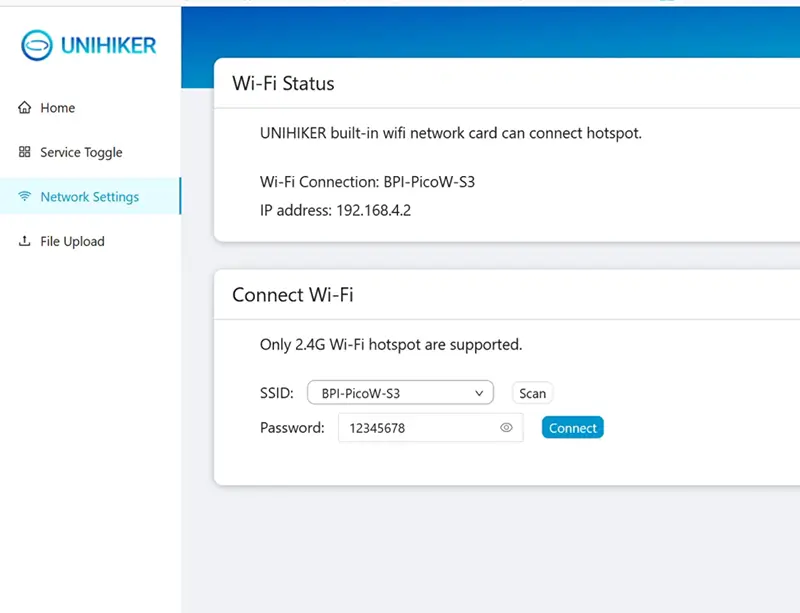
It took me a few times (both scanning and then connecting) before I saw the Access Point in the list. Once I did connect though I’ve never had to return to this page. As soon as the Banana Pi PicoW S3 is on the Unihiker attempts to connect and make a socket connection which in turn just works every time.
The values seen in this screenshot represent the ones we setup in the code prior. If you changed the WiFi SSID or password there you’ll need to use those here as one would expect.
Getting the Remote Ready
The next step is to upload the images and code. With the SSH connection to the Unihiker ready you need only drag and drop the associated images folder from the code repository to get them on the device. These images include ones for each button, a background with the title, and a splash screen.
Like the images the unihiker_remote.py can be dragged over. Once on the device you can get to the code (assuming it was placed in the root) by long pressing the side button to open the menu, selecting “2 - Run Programs”, selecting the “root” folder, and then selecting the program from within there.

Code Breakdown
The code for the Unihiker here isn’t too complex. Like earlier I’ll go into some detail about various elements but the code itself should be referenced for use on the device.
server_ip = '192.168.4.1'
server_port = 8080
As mentioned earlier the access point’s address for me was this one so I setup the Unihiker remote to connect to this address.
def send_command(s, command):
    try:
        s.sendall(command.encode())
        print(f"Sent: {command.strip()}")
    except (BrokenPipeError, ConnectionResetError, OSError):
        print("Connection lost. Reconnecting...")
        s.close()
        s = connect_to_server()
        s.sendall(command.encode())
    return s
I setup a send_command method to send commands to the device.
def connect_to_server():
    while True:
        try:
            s = socket.socket(socket.AF_INET, socket.SOCK_STREAM)
            s.connect((server_ip, server_port))
            print("Connected to server")
            return s
        except (ConnectionRefusedError, OSError) as e:
            if isinstance(e, OSError) and e.errno == 101:
                print("Network is unreachable. Retrying in 5 seconds...")
            else:
                print("Connection failed. Retrying in 5 seconds...")
            s.close()
            time.sleep(5)
Likewise I setup a method called connect_to_server that attempts to connect to the server but in the event of failure it retries 5 seconds later.
def initialize_gui():
    gui = GUI()
    gui.draw_image(x=0, y=0, w=320, h=320, image="images/remote.png")
    return gui
I’ve encapsulated some logic here to initialize the GUI setting up the initial splash image and returning the GUI object.
def draw_buttons(gui):
    commands = {
        'turn_left': 'images/arrows-turn-left.png',
        'turn_right': 'images/arrows-turn-right.png',
        'left_forward': 'images/arrows-top-left.png',
        'forward': 'images/arrows-top.png',
        'right_forward': 'images/arrows-top-right.png',
        'left': 'images/arrows-left.png',
        'stop': 'images/stop.png',
        'right': 'images/arrows-right.png',
        'left_backward': 'images/arrows-bottom-left.png',
        'backward': 'images/arrows-bottom.png',
        'right_backward': 'images/arrows-bottom-right.png',
        'obstacle_avoidance': 'images/obstacle-avoid.png'
    }

    button_positions = [
        ('turn_left', 30, 80), ('obstacle_avoidance', 90, 80), ('turn_right', 150, 80),
        ('left_forward', 30, 140), ('forward', 90, 140), ('right_forward', 150, 140),
        ('left', 30, 200), ('stop', 90, 200), ('right', 150, 200),
        ('left_backward', 30, 260), ('backward', 90, 260), ('right_backward', 150, 260)
    ]

    for command, x, y in button_positions:
        gui.draw_image(x=x, y=y, w=60, h=60, image=commands[command], onclick=lambda cmd=command: button_click(cmd))
I’ve setup these two mappings. In retrospect I suppose I could have just put the images in the tuple for the button positions but I didn’t at the time. The logic loops over the button positions, uses the draw_image method on the gui to then draw them to the page. It uses the commands mapping to figure out the correct image to use. You can see in the onclick lambda it sets the variable cmd to the value of command which it then in the lambda uses.
def button_click(command):
    global connection_socket
    connection_socket = send_command(connection_socket, command)
When the button is clicked it then runs this code sending that command to the socket.
Board("UNIHIKER").begin()
gui = initialize_gui()

connection_socket = connect_to_server()

gui.draw_image(x=0, y=0, w=320, h=320, image="images/background.png")
draw_buttons(gui)

while True:
    time.sleep(1)
The main logic is seen here – it initializes the Unihiker board, the GUI (and splash as mentioned above), attempts to connect to server, once that completes it adds the background, and then draws the buttons. Given the rest of the logic is handled in callbacks the loop logic simply sleeps each iteration to keep the program alive.
Next Steps?
I could imagine further augmenting this control to display sensor data and display it on the remote as you control it. It would also be really cool to use an onboard Xiao ESP32S3 Sense to get a low resolution image to display to allow for remote control.
Image Creation Process
To help aid me with the remote control design I utilized ChatGTP’s image generation features. The nice thing about relying on a tool like this is that it can create lots of content with a similar theme allowing your images to work well together as you design an interface.
To generate the images I started with a simple prompt:
I’m designing a gamepad and need a bunch of arrow buttons to see which I’d prefer – give up and up right for each design and make sure the design can be flipped or rotated without issue for those two (omnidirectional)
This led to it responding with ASCII art so I responded:
Image generation
Which started generating images.
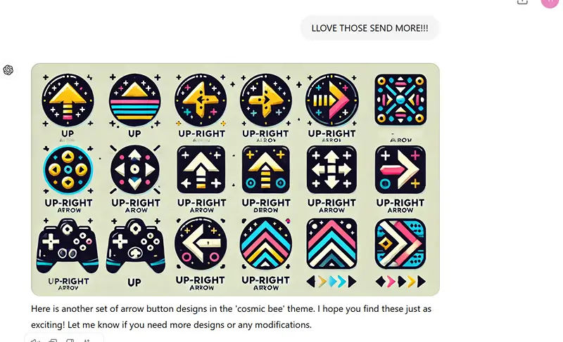
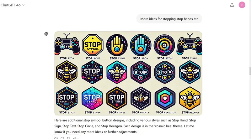
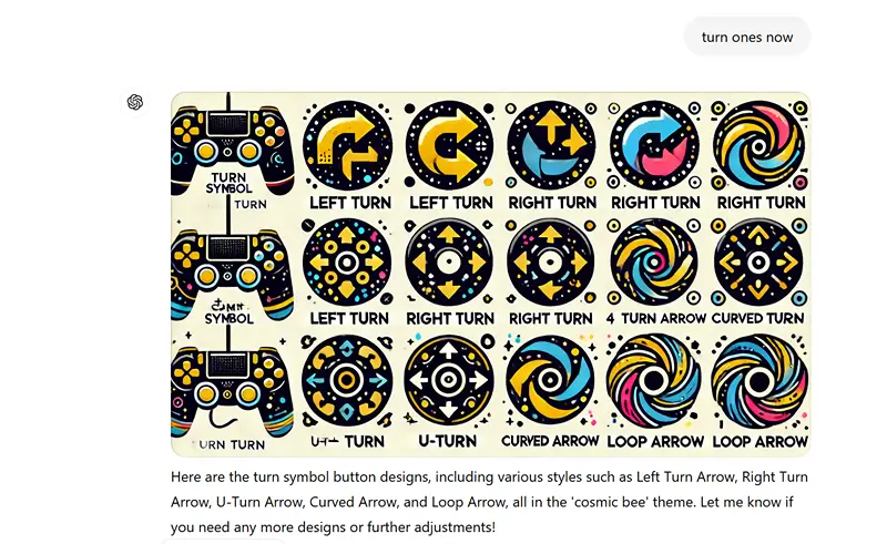
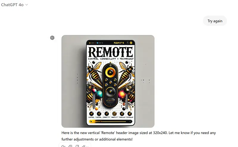
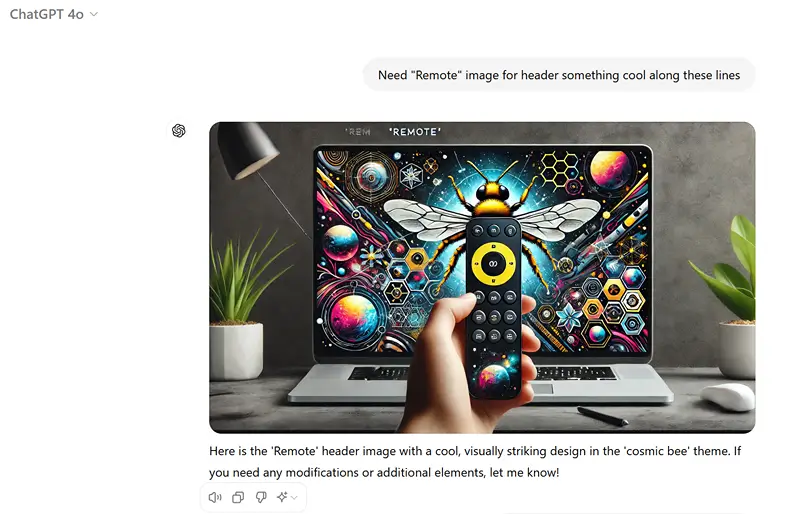
I’ve included screenshots of the exchange here as a gallery.
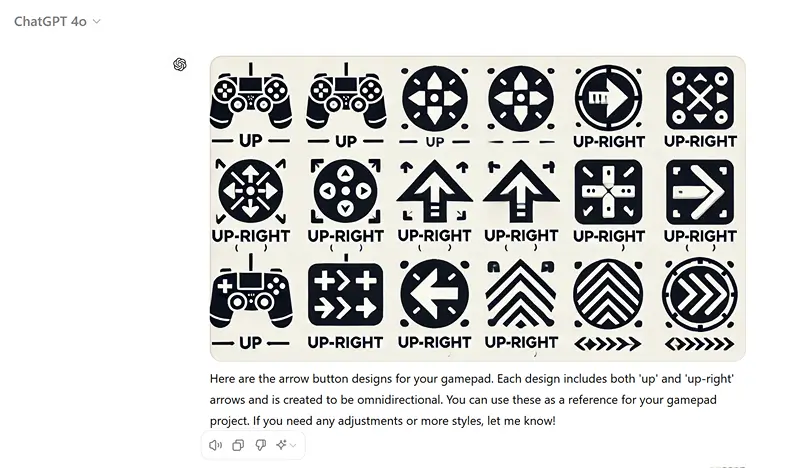

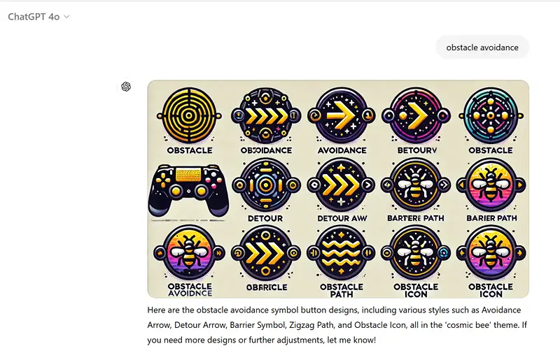
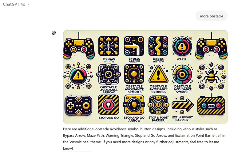
After this I took the images, cut out the components and exported them for as individual images. For the arrows I flipped them around as needed horizontally and vertically to have one for each direction. I also turned them 45 degrees such that they pointed toward each corner and side.
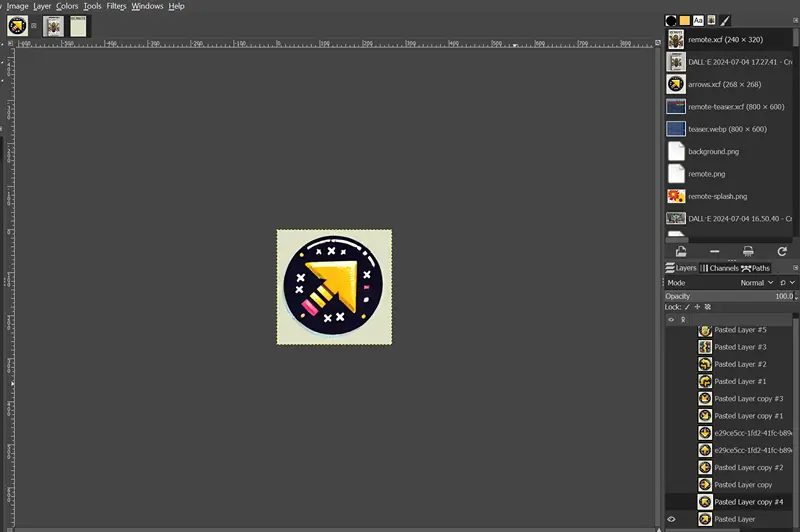

After exporting them I took the images and used them for the project.