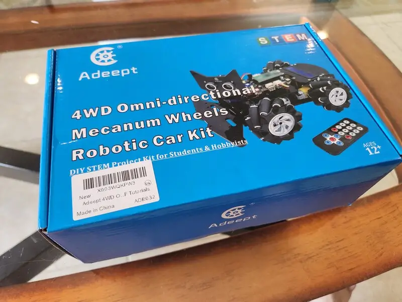
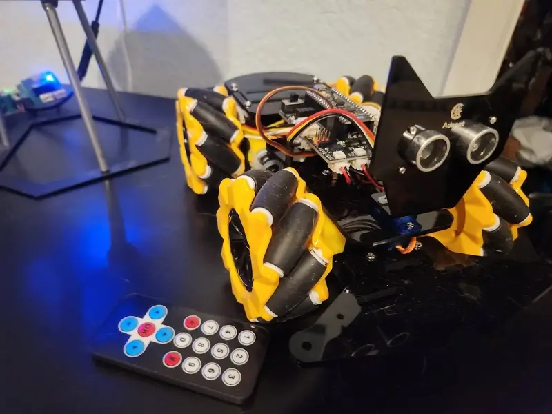
For this post I’m taking a look into the Adeept 4WD Omni-directional Mecanum Wheels Robotic Car Kit for ESP32-S3. It’s a robotic car created by Adeept that utilizes a Banana Pi PicoW S3 as its microcontroller. I was excited to try this product out as I have several Adeept cars and this one’s features really stood out to me.
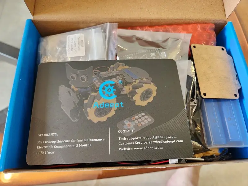
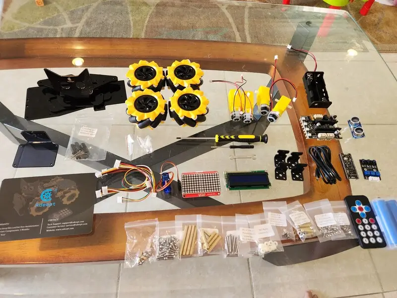
First I’d like to thank Adeept for sending me the car. It was fun to put together with my daughter. What’s really impressive though is this motor shield they put together as it has a lot of extensibility while providing a ton of built in features.
The MCU, Banana Pi PicoW S3
The Banana Pi PicoW S3 is a neat microcontroller. You can view a more expansive breakdown of its features optionally but I’m going to quickly give the rundown here:
- Onboard WS2812
- Emerald LED on GPIO25
- 8MB QSPI Flash (plenty of room for a program)
- Tons of GPIO
- Bluetooth
- WIFI
- Interfaces: GPIO, ADC, TOUCH, PWM, I2C, SPI, RMT, I2S, UART, LCD, CAMERA, USB, JTAG
So a very capable microcontroller. It’s capable of running MicroPython and CircuitPython. They also released the schematic. Their documentation goes into some detail about setting up CircuitPython. For the purposes of this article and my associated video I’m using CircuitPython. The only thing I’d complain about at all so far with the microcontroller is the choice of solder points for the boot menu. I assume I could solder a button there to make it easier but once I had CircuitPython on the device I no longer had a need to do it.
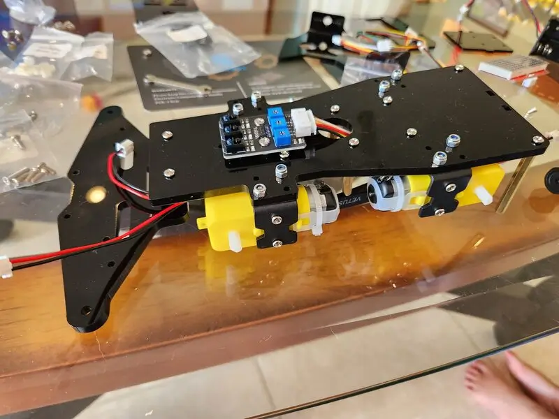
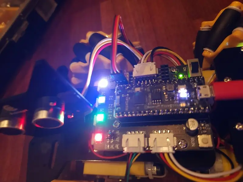
The Adeept Motor Expansion Board
The board the project comes with is really impressive and has a ton of features and expansibility.
They provide a PDF with a breakdown of the features but I’ll quickly go over them here:
- 7V-12V input voltage (provided by the kit’s 18650 battery holder)
- An onboard power switch
- 4 Servos
- Buzzer
- 4 WS2812s
- IR Receiver
- 4 Motors
- Ultrasonic Connector
- 2 I2C Connectors
- Expansion ports for GPIO 27
- WS2812 expansion port
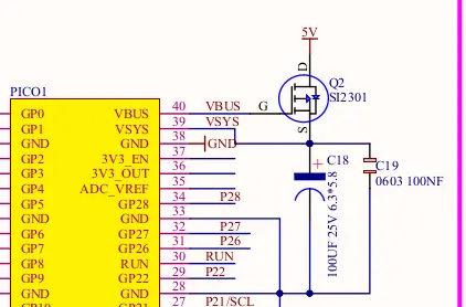
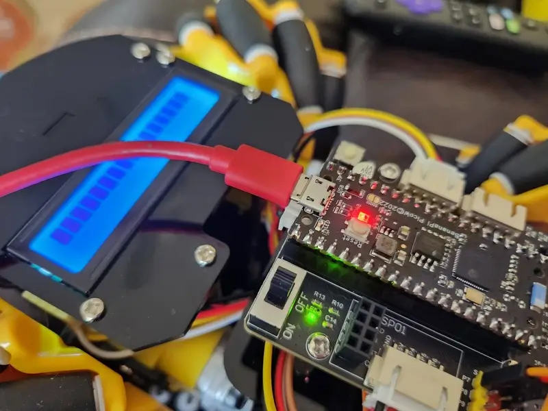
In addition the shield appears to be designed to protect against issues where both the USB and the power switch is enabled. You can see from the associated image when the VBUS line from the microcontroller (which has a diode between VBUS and VSYS) is brought to a high voltage it causes the P-Channel mosfet to conduct.
Getting Started
The first step to the build is to get the associated documentation from Adeept. They provide a zip file that contains, a PDF around assembly, code, schematic, and some prepackaged components to help with development (the CircuitPython uf2, some tooling, etc.).
To aid with development I flashed the latest CircuitPython version and associated bootloader to the device. I also downloaded the latest bundle for CircuitPython 9.x as many of these libraries will be needed to fully run the car.
Take a look at the imports of files you’re using and add the libraries accordingly. For example if you see the neopixel get imported add neopixel.mpy to the /lib folder on the device.
Assembling the Robot
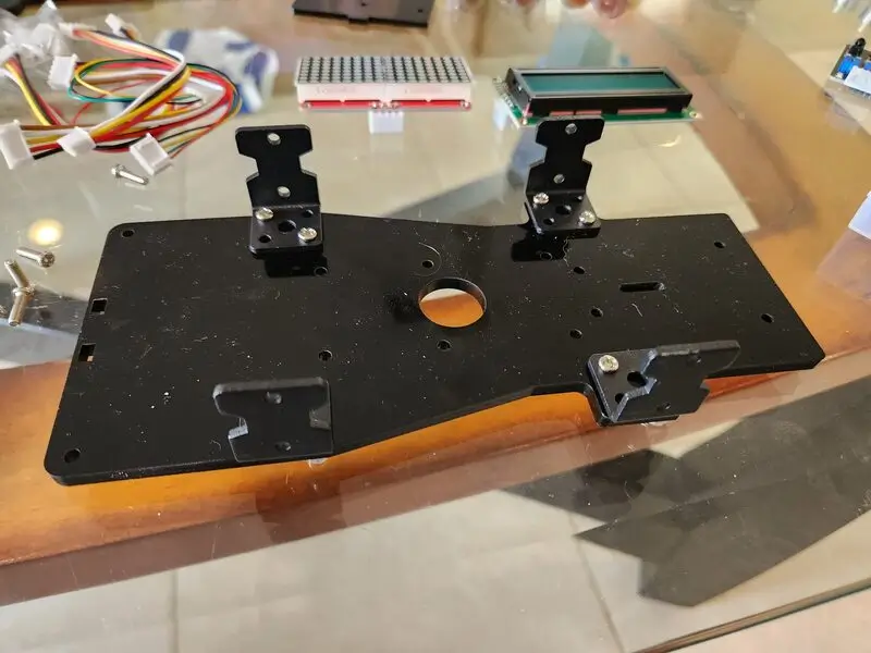
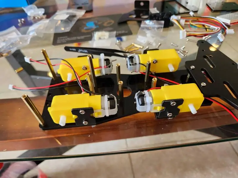
Adeept has done a great job documenting the setup process in their Tutorials/Assemble folder found within the project zip.
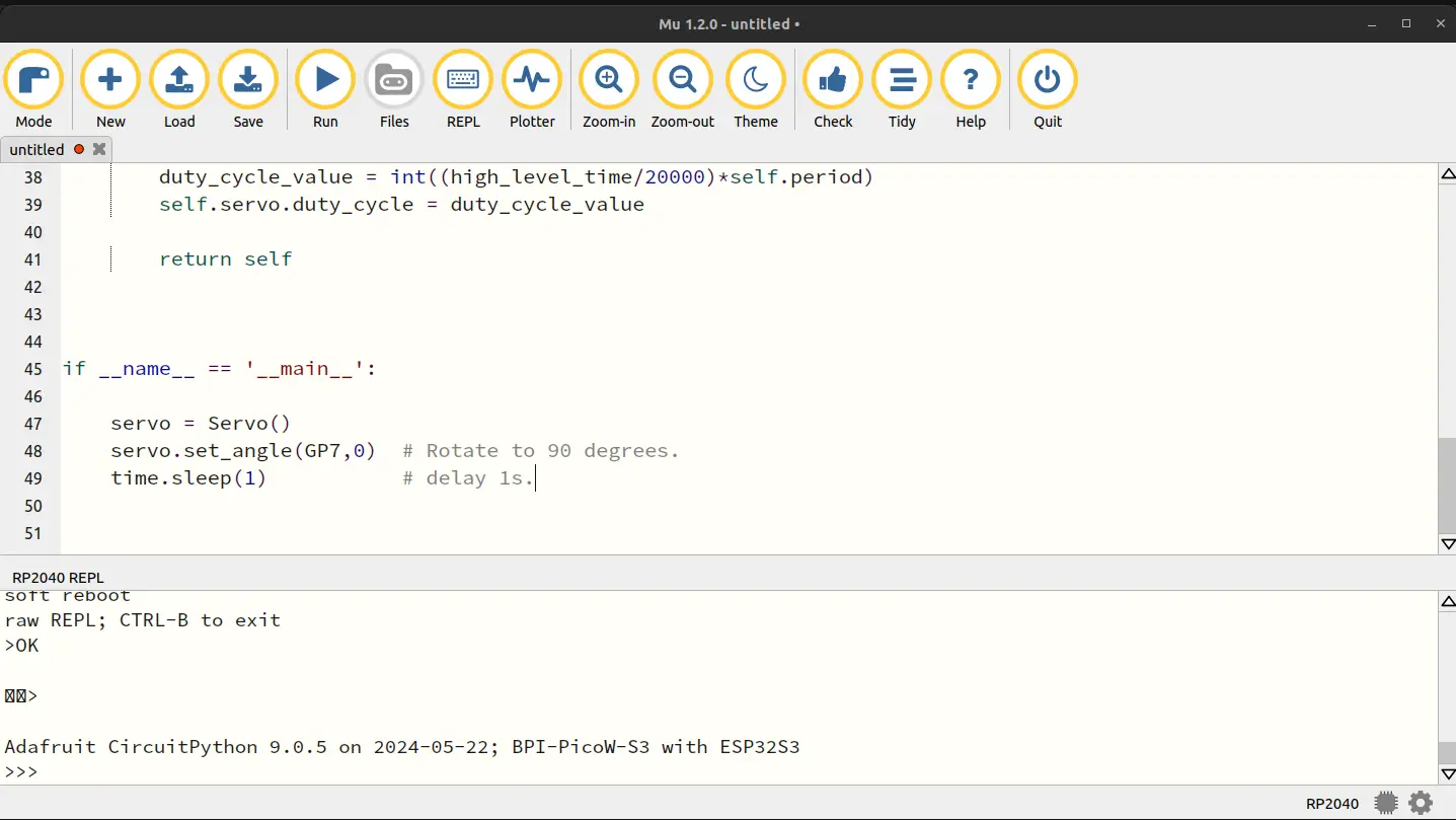
The first file you’ll find in the Tutorials/Assemble folder is one that documents the need to set the servo motor to the 90 degree position prior to assembly. I found that with Mu I needed to use the RP2040 mode in order to see the “Run” button. It worked well enough though and I was able to align the servo with no issues.
With the servo setup most of the rest of the setup is just a matter of following along with the fairly clear instructions in the Assemble.pdf file. I won’t copy it all here as you can find videos online showing folks assemble it and the guide is great.
The only issues I ran into I’d caution about are:
- Wheel orientation
- Servo tightening
Wheel orientation
The guide goes into detail but the general setup has the wheels creating an X orientation with the orientation as L R and a back row of R L. This is important as the build is able to perform these cool directional movements through these unique wheels and configuration. It’s important to properly set this up or your car will not properly function.
Servo tightening
One thing to keep in mind when attaching the head of the robot to the servo is the amount of tightening required for attaching the robot head to the servo. I initially tightened mine far too much leading to the head having a limited servo range.
Testing the Robot
To test the robot I decided I’d run through all of the examples provided confirming everything worked accordingly. One thing to note, and I’m not sure if it’s normal or not but it seems mostly harmless, during the boot process the front left wheel goes crazy for a moment so I need to lift the robot up when turning it on to avoid it hurting itself. It’s fine after that so I’m wondering if it’s some sort of pin driven high at boot situation but haven’t looked heavily into it.
Lesson 1 Blink
import board
import digitalio
import time

ledpin = digitalio.DigitalInOut(board.GP25)

while True:
    ledpin.switch_to_output(value=1) # Output high level.
    print("Light on...")
    time.sleep(1) # Delay 1s.
    ledpin.switch_to_output(value=0) # Output low level.
    print("Light off.")
    time.sleep(1) # Delay 1s.
The code here is fairly straightforward. You can see from the Banana Pi schematic
Here is the relevant section:
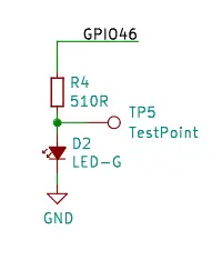
You can see the GPIO 46 on the board is directly used to source the current for the LED. Now you’re probably thinking but we just used GP26 above, right? The board’s GPIO mapping is handled via a configuration file:
    { MP_ROM_QSTR(MP_QSTR_GP25), MP_ROM_PTR(&pin_GPIO46) },
    { MP_ROM_QSTR(MP_QSTR_LED), MP_ROM_PTR(&pin_GPIO46) },
Which as you can see performs this mapping.
Lesson 2 WS2812 LED Control
import time
import board
import neopixel

pixels = neopixel.NeoPixel(board.NEOPIXEL, 1, brightness=0.1)

while 1:
    pixels[0] = (255,0,0)
    pixels.show()
    time.sleep(0.5)
    pixels[0] = (0,255,0)
    pixels.show()
    time.sleep(0.5)
    pixels[0] = (0,0,255)
    pixels.show()
    time.sleep(0.5)
    pixels[0] = (255,255,255)
    pixels.show()
    time.sleep(0.5)
It’s a fairly simple example but let’s dig in just for clarity.
First we see we’re relying on the board’s NEOPIXEL named pin. We can discover which GPIO this corresponds to by looking over that commit for adding the board.
{ MP_ROM_QSTR(MP_QSTR_NEOPIXEL), MP_ROM_PTR(&pin_GPIO48) },
So we know it’s related to pin 48. We can see this from the schematic as well:
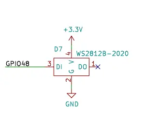
What’s interesting to me is the datasheet for the WS2812B-2020 shows it takes an input voltage of 3V7 but the Banana Pi PicoW shows a 3V3 input voltage. I know it’s working as I can see it but was surprised given the datasheet I found.
WS2812B are easy to control with the neopixel library. From a hardware perspective they are also easy to place. Each one has an input pin and output pin allowing them to be chained together. Generally, like in the case of the motor board, you want a friendly neighbor capacitor next to each to avoid issues but it’s fine with a single onboard LED like this.
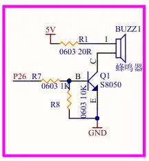
Lesson 3 Buzzer Control
In this lesson the Adeept team show how to control the associated buzzer.
self._buzzer = pwmio.PWMOut(board.GP26, duty_cycle=0, frequency=440, variable_frequency=True)

def playtone(self, frequency):
    self._buzzer.duty_cycle = 65535 // 2  # Half-full duty ratio
    self._buzzer.frequency = frequency

while True:
    buzzer.playtone(1500)
    time.sleep(1)
    buzzer.playtone(1200)
    time.sleep(1)
I’ve attached the important pieces above. They setup pin 26 as a PWM output. They then set the frequency updating it to various tones at a 1 second interval. Additional frequencies could have been used here as well.
Here is the associated part of the motor shield schematic for the buzzer:
Lesson 4 Servo Control
This is a fun one if you have kids. Upon running this script the robot head will turn from one side to the other. You may remember the setup instructions had us run the servo setup script initially and as such the robot is able to move the entire 180 degree range in front of it.
The frequency of the servo is set at 50 Hz which is the frequency required for the Adeept servos.
They provide a mapping function to help set the servo location. When the values for the hardcoded angle and pwm min and max the function becomes:
return (x - in_min)/(in_max - in_min)*(out_max - out_min) + out_min
return (angle - -90)/(90 - -90)*(2500 - 500) + 500
return (angle + 90)/(180)*(2000) + 500
For -90 that would give us: 0/180*2000 + 500 or 500 For 0 that would give us 90/180 * 2000 + 500 or 1500 And for 90 that would give us 180/180 + 2000 + 500 or 2500
With the period of 65535 these become: -90 duty cycle: 500/20000 = 2.5% duty cycle 0 duty cycle: 1500/20000 = 7.5% duty cycle 90 duty cycle: 2500/20000 = 12.5% duty cycle
The 20000 here is 1000000/50 which accounts for the 50 Hz frequency.
These values correspond with the expected PWM duty cycles to turn the servo from the -90 to the +90 range (180 degrees total).
This was helpful for me as I haven’t done much with servos so spending the time learning why this worked has given me a boost of confidence with robotics.
Lesson 5 Ultrasonic Control
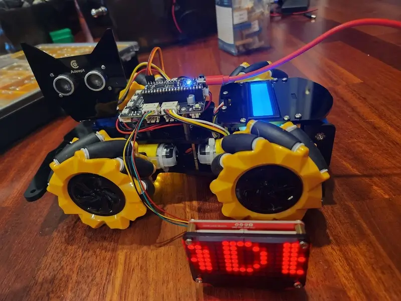
The next lesson they show how to control the Ultrasonic distance module. They used a common module for the robot, the HC-SR04. I have a couple of these on hand from random electronics kits in the past but I am a big fan of using them as literal eyes of the robot as the Adeept team did here. My daughter calls the robot the “Kitty Robot” as a result and I think it really helps the module blend in.
Going to highlight a few sections of this example:
#Define output(trig) and input(echo) Pin.
self._trig = pwmio.PWMOut(board.GP3, frequency=10000, duty_cycle=0)
self._echo = digitalio.DigitalInOut(board.GP2)
self._echo.direction = digitalio.Direction.INPUT

def get_distance(self):
    # Send a pulse to the trig Pin
    self._trig.duty_cycle = 0
    time.sleep(0.1)
    self._trig.duty_cycle = 65535
    time.sleep(0.1)
    self._trig.duty_cycle = 0
    # Wait for the echo pin to become high
    while self._echo.value == False:
        pass
    # Record start time
    start = time.monotonic_ns()
    # Wait for the echo pin to lower
    while self._echo.value == True:
        pass
    # End of record time
    end = time.monotonic_ns()
    # Calculate the duration of the pulse (nanosecond)
    duration = end - start
    # Distance (cm) calculated based on the speed of sound (343 m/s)
    distance = ((duration / 2)/1000) * 0.0343
    # Return distance value
    return distance
The trigger is set as a PWM output while the echo as an input. The trigger sends a pulse, the logic waits for the response, and then it uses a calculation based on the speed of sound to determine the distance in cm.
Really straightforward and a neat way to get the distance of an object. These sensors are readily available (Adeept sells them for example) and they are useful to have on hand for robotic projects.
An example output with my hand in front for the two small distances:
Distance: 808.62cm
Distance: 888.69cm
Distance: 16.22cm
Distance: 13.61cm
Distance: 850.49cm
Distance: 937.37cm
Distance: 1170.79cm
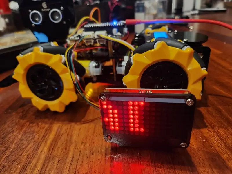
Lesson 6 LED Matrix
This LED matrix is setup using the adafruit_ht16k33 library. This library, and the associated chip it’s controlling, allows you to very easily control the LED status of LED matrixes via their rows and columns.
i2c = busio.I2C(board.GP21, board.GP20)
display = matrix.Matrix16x8(i2c)
The board has pin GP21 as SCL and GP20 as SDA.
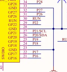
You can see these were selected as the I2C pins for the microcontroller and used on the board as such.
Let’s dig into the Letter A:
letter_A = [
    0x0c, 0x1e, 0x33, 0x33, 0x3f, 0x33, 0x33, 0x00
]
These are the columns for the 8 rows indicating which pixels are enabled.
`0x0c`:`00001100`
`0x1e`:`00011110`
`0x33`:`00110011`
`0x33`:`00110011`
`0x3f`:`00111111`
`0x33`:`00110011`
`0x33`:`00110011`
`0x00`:`00000000`
If you look closely you can see the letter A there. That’s pretty much all there is to this. The logic for the example is setup to take the word length, treat each letter like it’s 8 bits wide (as they are) and then shifts over it from start to end displaying all the letters by selectively enabling those pixels for the given scroller at each point. In the example the logic is setup to call display.pixel for columns not visible given the shift which explains how it’s rendering across the entire 16 columns.
Adjusting their example code to something like:
while True:
    for shift in range((word_length * display_width) + 1):
        display.fill(0)

        for i in range(word_length):
            for row in range(8):
                for col in range(8):
                    if (word[i][row] >> col) & 0x01:
                        if col + i * display_width - shift + 1 <= 3:
                            display.pixel(col + i * display_width - shift, row, 1)

        display.show()
        time.sleep(0.2)
Will only render the Adeept message in the first 3 columns.
This scrolls it across the first 8:
if col + i * display_width - shift + 1 <= 8:
Anyhow the logic here is pretty straightforward:
        for i in range(word_length):
            for row in range(8):
                for col in range(8):
                    if (word[i][row] >> col) & 0x01:
It loops over each letter and then for each row and column it checks if the pixel should be enabled and if it should subsequently enables it (using that shift value so it may or may not be actually visible if it’s not in the first -15 columns post shift).
Lesson 7 Robot WS2812 LED Control
This lesson is very similar to the last WS2812 one just it’s using the normal sized version versus the 2020 SMD variant found on the Banana Pi PicoW S3. The neat thing about this though is Adeept has provided an additional extension output. They had the foresight to put that extension which is just awesome as it opens the door for lots of custom improvements (underlighting, additional displays, etc.) Not sure how much current it can source though so I’ll have to update here after I ask the Adeept team.
self._led_num = 4 #  LED number
self._pin = board.GP11    # GPIO11
As you can see the example initializes 4 LEDs on GPIO 11 which is the one selected as the Neopixel on board LEDs. It then has some logic that helps manage the LED state.
Nothing against this example but I want to have fun with my LEDs (I’m a big fan of LEDs afterall) so you can look into this example further as an exercise but I’m going to explain how to make the thing go rainbow mode.
A more simple example of Neopixels is just setting the LED values directly:
import board
import neopixel

pixel = neopixel.NeoPixel(board.GP11, 4, pixel_order=neopixel.GRB)
brightness = 0.2
pixel[0] = (255*brightness, 0*brightness, 0*brightness)
pixel[1] = (0*brightness, 255*brightness, 0*brightness)
pixel[2] = (0*brightness, 0*brightness, 255*brightness)
pixel[3] = (255*brightness, 255*brightness, 255*brightness)
In this example I have set the 4 pins individually setting the first to red, the second to green, the third to blue, and the last to white by enabling all of the colors.
But that’s no fun, let’s import the circuit python animation library and make it do a rainbow chase.
First, you will need to include the adafruit_led_animation library in your lib folder on the device adafruit_led_animation.
import board
import neopixel
from adafruit_led_animation.animation.rainbowcomet import RainbowComet

pixels = neopixel.NeoPixel(board.GP11, 4, pixel_order=neopixel.GRB)
rainbow_comet = RainbowComet(pixels, speed=0.1, tail_length=7, bounce=True)

while True:
    rainbow_comet.animate()
This causes a rainbow comet of 7 pixels to run across the 4 WS2812s. There are a lot of other animations available so feel free to check them out.
Unfortunately not of my cables were small enough to use with the expansion LED port. I’ll have to pick up a smaller cable for that in the future to try with some of my LED strips. I’d imagine goven it’s on P11 as well it’s as simple as just increasing the number of LEDs in the code once you have it attached.
Lesson 8 Motor Control
For this lesson they have you control the motor attached via the first port. They suggest you test each motor in this way.
They have a few examples commented out in the code to show how you could handle some of the other motors as well but I’ll focus on the test code they are suggesting folks run here:
self.motor_left_front(1, 1, 100)
time.sleep(2)
self.motor_left_front(1, -1, 100)
time.sleep(2)
They have this logic as part of the test where the first motor moves forward for 2 seconds and then moves backwards for 2 seconds.
    # Control the M1 motor (left front).
    def motor_left_front(self, status, direction, speed):
        if status == 0: # stop.
            Motor_LF_Dir.value = False
            Motor_LF_PWM.duty_cycle = 0
        else:
            value = int(map(speed, 100, 0, 65535, 0))

            if direction == Dir_forward:
                Motor_LF_Dir.value = False
                Motor_LF_PWM.duty_cycle = value
            elif direction == Dir_backward:
                Motor_LF_Dir.value = True
                Motor_LF_PWM.duty_cycle = 65535 - value
The logic here checks the status which appears to be 0 or anything else and in the event it is 0 it resets the direction to forward (via the false state) and sets the duty cycle to 0. When the status is not 0 it maps a speed from 0 to 100 to the full range of the PWM duty cycle.
This is the mapping function given:
def map(x,in_max, in_min, out_max, out_min):
    return (x - in_min)/(in_max - in_min)*(out_max - out_min) + out_min
You could replace this to give finer control in the lower range by weighting the lower end more heavily with:
def map(x, in_min, in_max, out_min, out_max, weight=2.0):
    normalized_x = (x - in_min) / (in_max - in_min)
    weighted_x = normalized_x ** weight
    return weighted_x * (out_max - out_min) + out_min
This would produce values like the following:
Number: 0
Original Mapped 0-255: 0.0000
Original Mapped 0-65535: 0.0000
Weighted Mapped: 0.0000
Number: 20
Original Mapped 0-255: 13107.0000
Original Mapped 0-65535: 13107.0000
Weighted Mapped: 2621.4000
Number: 40
Original Mapped 0-255: 26214.0000
Original Mapped 0-65535: 26214.0000
Weighted Mapped: 10485.6000
Number: 60
Original Mapped 0-255: 39321.0000
Original Mapped 0-65535: 39321.0000
Weighted Mapped: 23592.6000
Number: 80
Original Mapped 0-255: 52428.0000
Original Mapped 0-65535: 52428.0000
Weighted Mapped: 41942.4000
Number: 100
Original Mapped 0-255: 65535.0000
Original Mapped 0-65535: 65535.0000
Weighted Mapped: 65535.0000
As you can see the new approach increases the control at the lower end of the mapping. The weight value could be adjusted further to find what feels right there. These cars don’t move too fast though so I may keep the linear approach just wanted to highlight it while looking into the code.
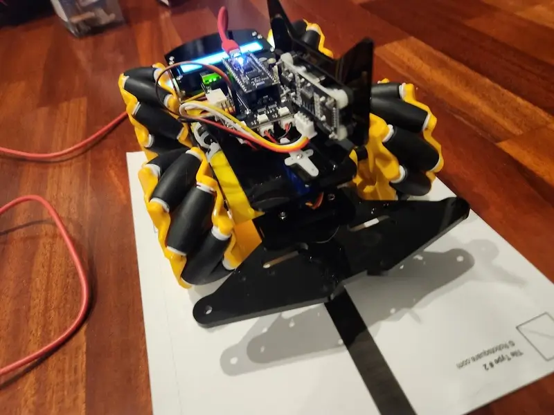
Lesson 9 Line Detection
This example is one that works best with electrical tape or printed out lines versus pen on paper. I found some line follow tiles online and printed out the second page which was a single line across. I’ve placed the robot on the paper in such a way that the middle and right line detectors are able to see the line while the left is hitting the white of the paper.
You can see my output here:
left: False, middle: True, right: True
left: False, middle: True, right: True
left: False, middle: True, right: True
left: False, middle: True, right: True
left: False, middle: True, right: True
Just to quickly hover over the important elements of the example:
ir_left = digitalio.DigitalInOut(board.GP4)
ir_left.direction = digitalio.Direction.INPUT

ir_middle = digitalio.DigitalInOut(board.GP5)
ir_middle.direction = digitalio.Direction.INPUT

ir_right = digitalio.DigitalInOut(board.GP6)
ir_right.direction = digitalio.Direction.INPUT
It sets each of the associated pins as inputs. It then just reads their value each iteration of the loop and displays it. To control the car based on this you’d monitor the state of the three and turn the vehicle slightly when it begins to favor a given side allowing you to center out.
Lesson 10 IR Control
This lesson was one of the more difficult given some issues with the remote control I was sent with the kit. For some reason it seems to send the same value multiple times in a row even when I switch keys. At first I thought maybe the IR sensor on board was bad or just had really bad range but I see it recognizing the remote just not the right keys. I can on occasion get it to work consistently.
You should be able to hit each button and have it display a Command: # where the # is the command number or name. For me it repeated a lot of the same values but I assume this is a controller bug and shouldn’t happen in most cases.
Command: 1
Command: 2
Command: 3
Command: 3
Command: 3
Command: 4
Command: 5
Command: 6
Command: 7
Command: 8
Command: 9
Command: *
Command: #
Command: up
Command: right
Command: down
Command: left
Command: ok
I’ll take a look in the future once I get ahold of a Grove IR Emitter. At the moment I don’t have another IR device to test sending codes with.
The logic sets up GP22 as the IR receiver and then loops over checking for a received signal. The IR API library handles actually getting the command out of the IR signal.
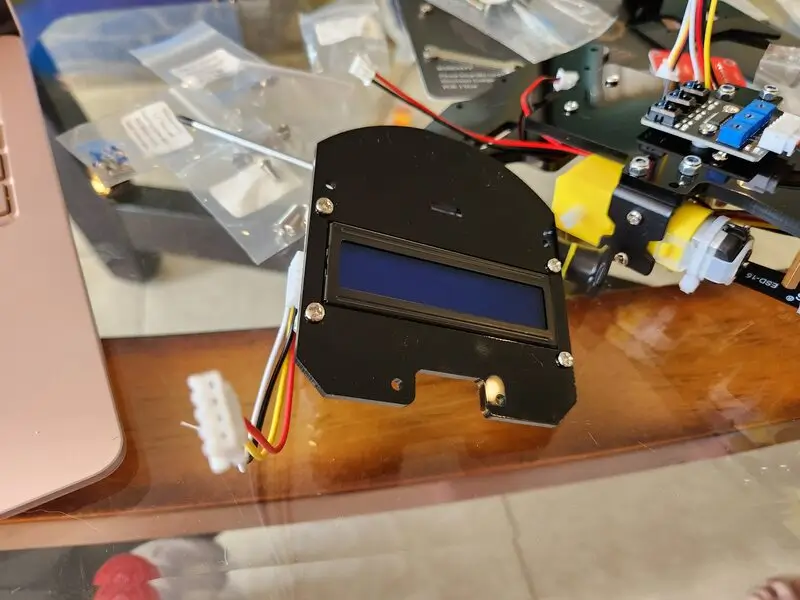
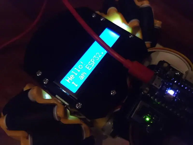
Lesson 11 LCD Text
This example is a fairly simple one.
The logic imports the associated LCD related logic:
from lcd.lcd import LCD
from lcd.i2c_pcf8574_interface import I2CPCF8574Interface
from lcd.lcd import CursorMode
Connects to the LCD over i2c:
# Talk to the LCD at I2C address 0x27.
lcd = LCD(I2CPCF8574Interface(busio.I2C(board.GP21, board.GP20), 0X27), num_rows=2, num_cols=16)
And then it proceeds to write text first “Hello!” followed by a newline “\n” and then after a second it writes out “I am ESP32.”:
lcd.clear()
lcd.print("Hello!\n")
time.sleep(1)
lcd.print("I am ESP32.")
In this way you can write whatever you want here.
Lesson 12 Print Info
This was a simple lesson that just prints out some board info including onboard memory.
There’s also a second component around reading the temperature I’ll discuss here. The board uses the analog IO input from GP4 and then converts that value into Celcius.
sensor_temp = analogio.AnalogIn(GP4)
conversion_factor = 3.3 / (65535)

reading = sensor_temp.value * conversion_factor
temperature = 27 - (reading - 0.706)/0.1721
print("Temp: {:.2f}°C" .format(temperature))
Temp: 13.33°C
Lesson 13 Avoidance
Firstly, you’ll need to add the associated libraries. On my own Banana Pi PicoW S3 I was running into an error trying to run this at first as I had an older incompatible version of adafruit_ht16k33 setup in the lib folder. Replacing that with the one from my circuitpython9 library bundle fixed the issue. If you see messages of an incompatible mpy file for the car I suggest trying to update all of your associated libraries for the current ones.
This example illustrates controlling the robot based on the state of the sensors. It goes forward at varying speeds while detecting obsticals and, when encountered, attempts to turn its ultrasonic sensor to see if moving in a different direction is more ideal. This worked for the most part but it often gets stuck as the logic is fairly simple for example purposes and it looks for objects at a very close range. Either way it worked for the most part going straight, turning out of a corner where one side was open, etc.
Lesson 14 IR Remote Control Car
This exercise has you control the car motors via the remote. Unfortunately given the remote issues I’ve noted it is a bit hard to control the car. Often it sends the wrong command from the remote which ends up causing the car to behave unexpectedly. It’s too random for me to really use it though.
Lesson 15 Line Follow
This one took me a little bit of effort to get right. I had to calibrate the 3 line sensors a bit until I was able to get the robot to follow it. Once it was calibrated though the robot mostly handles the line without issue slowly changing directions as it moves.
ir_left = digitalio.DigitalInOut(board.GP4)
ir_left.direction = digitalio.Direction.INPUT

ir_middle = digitalio.DigitalInOut(board.GP5)
ir_middle.direction = digitalio.Direction.INPUT

ir_right = digitalio.DigitalInOut(board.GP6)
ir_right.direction = digitalio.Direction.INPUT
As the line follow logic previous showed this first sets each pin as an input. Then the logic loops over getting the current state and depending upon that modifies the direction the robot moves. For example if it notices [0, 1, 0] for the state of the sensors it moves forward as it indicates the line is present.
One tricky thing about this example is that the logic is setup to go in a circle if it can’t find the line. At first I thought something was wrong as a result of that but in reality, as mentioned above, I needed to further configure the sensors prior to it detecting it correctly and properly following the line.
Lesson 16 Follow Function
This lesson uses the ultrasonic module as a means to figure out if the car should move forward or stop. It’s fairly simple just checking the ultrasonic range (like we saw previously) and acting accordingly.
Lesson 17 Comprehensive IR Remote Robot
Unfortunately as my IR controller is a bit faulty this one is a bit of a struggle for me to test. That said it’s pretty much the same as the last IR control one with the addition of the line tracking and follow behavior built in as additional commands for the remote. Clicking the # turns on the line tracking functionality and the * turns on the obstacle avoidance. The rest of the behavior of those modules is the same as the earlier lessons as they use the same code just called from this logic.
Lesson 18 WIFI Testing
For this lesson Adeept has you setup your secrets.py file and then subsequently use it for testing the board’s WIFI component.
It’s pretty straightforward but the logic first scans the networks:
networks = []
for network in wifi.radio.start_scanning_networks():
    networks.append(network)
wifi.radio.stop_scanning_networks()
networks = sorted(networks, key=lambda net: net.rssi, reverse=True)
for network in networks:
    print("ssid:",network.ssid, "rssi:",network.rssi)
The logic as part of this also outputs the RSSI strength which indicates how decent of a connection you’ll get from the network.
Then it connects to the WIFI using the secret values from that file:
wifi.radio.connect(ssid=secrets['ssid'],password=secrets['password'])
Outputs your IP address:
print("my IP addr:", wifi.radio.ipv4_address)
And then for good measure they test hitting Google.
hostname = "google.com"

pool = socketpool.SocketPool(wifi.radio)
addrinfo = pool.getaddrinfo(host=hostname, port=443) # port is required
print("addrinfo", addrinfo)

ipv4 = ipaddress.ip_address("8.8.4.4")
print("Ping google.com: %f ms" % (wifi.radio.ping(ipv4)*1000))
The reason port 443 was used above was that it’s the SSL port. If 80 had been used here it would have been normal HTTP traffic (sans the secure connection).
Lesson 19 WIFI Controller Test
For this lesson Adeept provides an app you can download to control the car. For the interest of explaining how it all works under the hood I’m going to use python on my laptop to control it instead from my terminal.
The first step is to push the code over to the robot per the tutorial. After that, you need to connect to the WIFI access point it is hosting. With that set you can send commands to it over the network.
I ran into a bug when I tried to run the code:
main.py output:
Traceback (most recent call last):
  File "main.py", line 9, in <module>
ImportError: can't import name lcd_putstr
This was imported via:
from BPI_PicoW_S3_Car import Buzzer, Servo, lcd_putstr, WS2812
I noticed in that file it was commented out:
#lcd_putstr = LCD1602()
Uncommenting it allows it to run.
I also removed the code around setting an IP address:
wifi.radio.set_ipv4_address(ipv4=ipv4, netmask=netmask, gateway=gateway)
It’s automatically assigned as part of the access point creation (it just confused me at first as the IP address selected by the code was never set but rather it had another IP for the AP). For me the address of the access point was 192.168.4.1.
Now that I’m on the network I’ll go ahead and connect to the device.
From the terminal app on Ubuntu I typed:
python3 to open a python shell.
import socket

# IP and port of the server
server_ip = '192.168.4.1'
server_port = 8080

def send_command(command):
    with socket.socket(socket.AF_INET, socket.SOCK_STREAM) as s:
        s.connect((server_ip, server_port))
        s.sendall(command.encode())
        s.close()
    print(f"Sent: {command.strip()}")
With that prepared I can start sending commands from the terminal.
First let’s look over the commands from Adeept:
| Direction | Command | Description |
|---|---|---|
| Up(1) | forwardStart | The buzzer sings |
| Down(2) | backwardStart | Adjust the initial angle of the servo |
| Left(3) | leftStart | lcd1602 displays Hello Adeept |
| Right(4) | rightStart | Servo rotates back and forth between 0-180 degrees |
| Up(5) | lookLeftStart | Control multiple colors |
| Down(6) | lookRightStart | Set all colors to red |
| Left(7) | downStart | Breathing lamp |
| Right(8) | upStart | Adjust the brightness to 0.1 |
| A | aStart | Activate an LED breathing light effect |
| B | bStart | Loop through NeoPixel to display four colors: red, green, blue, and white |
So we can trigger these (added comments to link):
send_command("forwardStart\n")    # Buzzer
send_command("backwardStart\n")   # Servo Angle Initialize
send_command("leftStart\n")       # Hello Adeept LCD
send_command("rightStart\n")      # Servo -90 to 90 positioning
send_command("lookLeftStart\n")   # WS2812 Color Change
send_command("lookRightStart\n")  # WS2812 Color Change Red
send_command("downStart\n")       # WS2812 Breathing Lamp
send_command("upStart\n")         # WS2812 Brightness 10%
send_command("aStart\n")          # Onboard WS2812 Breathing Light Effect
send_command("bStart\n")          # Onboard WS2812 RGBW Color Wheel
In this way you could control the robot’s behavior over the socket connection sending any sort of command and having it behave accordingly.
Lesson 20 WIFI Robot Control
Like the last lesson this one focuses on controlling the robot over its access point.
| Command | Description |
|---|---|
| forwardStart | Move the motor forward and display “Forward” |
| backwardStart | Move the motor backward and display “Backward” |
| leftStart | Move the motor left and display “Left” |
| rightStart | Move the motor right and display “Right” |
| downStart | Move the motor left forward and display “Left Forward” |
| upStart | Move the motor right forward and display “Right Forward” |
| lookLeftStart | Move the motor forward and display “Forward” |
| lookRightStart | Move the motor backward and display “Backward” |
| aStart | Start the avoid obstacles function |
| aStop | Stop the avoid obstacles function |
| bStart | Set servo angle to 0, display “functionA stop”, stop motor |
| cStart | Start the line tracking function |
| cStop | Stop the line tracking function |
| dStart | Display “functionC stop”, stop motor |
These appear to be the commands for this iteration.
import socket

# IP and port of the server
server_ip = '192.168.4.1'
server_port = 8080

def send_command(command):
    with socket.socket(socket.AF_INET, socket.SOCK_STREAM) as s:
        s.connect((server_ip, server_port))
        s.sendall(command.encode())
        s.close()
    print(f"Sent: {command.strip()}")
And with the commands:
send_command("forwardStart\n")    # Move motor forward, display "Forward"
send_command("backwardStart\n")   # Move motor backward, display "Backward"
send_command("leftStart\n")       # Move motor left, display "Left"
send_command("rightStart\n")      # Move motor right, display "Right"
send_command("upStart\n")         # Move motor right forward, display "Right Forward"
send_command("downStart\n")       # Move motor left forward, display "Left Forward"
send_command("lookLeftStart\n")   # Move motor forward, display "Forward"
send_command("lookRightStart\n")  # Move motor backward, display "Backward"
send_command("aStart\n")          # Start avoid obstacles function
send_command("aStop\n")           # Stop avoid obstacles function
send_command("cStart\n")          # Start line tracking function
send_command("cStop\n")           # Stop line tracking function
Interestingly enough I had to comment out that LCD reference to get the screen to show me the commands it was running so it seems it was commented out for that reason.
Back in that other Car file:
#lcd_putstr = LCD1602()
With this set you can see the commands reflect what’s sent on the LCD. One thing to note is oddly the obstical avoidance logic doesn’t seem to be using the ultrasonic module or avoiding anything like it did above in my video when I was using that functionality specifically. Not really sure as the servo does work and I’ve confirmed the other code shows it’s still working.
Lesson 21 Tiny UF2 Firmware Upload
Oops, I did this one first. It’s a good guide for the Banana Pi PicoW S3 though. I’d love to add Zephyr support for it in the future. I’ve added a board to Zephyr that got merged in (Xiao RP2040 support) so I have some experience with that.
Next Steps
With that set I’ve completed the material provided by Adeept to get started with the robot.
I have two projects in mind for using this robot I’ll be adding with subsequent articles now that I’ve completed the main elements:
- DFRobot Offline Voice Recognition Module control of the robot
- Seeed Studio Vision Sensor V2 human follow of the robot
I feel very lucky having been selected in the past to take part in the DFRobot and Seeed Studio trials for these products but they’re both awesome products on their own and mixed with Adeept’s car I think they’d create a cool display of functionality. Both companies have been great and support their products and developers in the community. They sponsor tons of contests and other events as well.
Thank you again Adeept especially for providing me the Banana Pi PicoW S3 Omni Car. It was a pleasure to put together, I learned a lot going through the tutorials especially around servo and motor control (areas I haven’t spent much time on historically) and I feel like as a result I’m in an even better place as a developer.
These additional tutorials will likely be added in the coming days as I’m going to actively work on these first prior to anything else.