Glowbug PD is a new WLED control board with USB power delivery and a selectable 5V or 12V output.
I love LEDs and I’m a huge fan of WLED a firmware that works on many Espressif microcontrollers to handle LED effects and control. WLED is fairly extensible with various usermods to handle things like audioreactive light displays, OLED screen output, and so on.
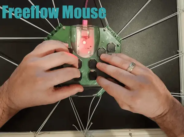
As a fan of all things LEDs I’ve purchased various devices on aliexpress with the intention of reworking their internals for use with the firmware. I have a few projects in various stages of development as a result such as a mouse bungee replacement board, a pac-man light reskin, and so on. For many of the projects a simple D1 mini hooked up directly to the light would probably be sufficient but if I wanted to use these lights for a long period of time I needed some nice-to-haves which would decrease the likelihood of any damage occuring to the board or lights. I had also read about USB PD allowing for up to 3A which would be more than sufficient for my needs. I’ve previously discussed the CH224K so opted to go that direction.
As such I wanted to design a board with the following features:
- USB power delivery power
- Uses a relay to keep power consumption in check
- Uses a fuse to prevent issues
- Capacitor for the LED line
- 3 or 4 wire support for LED strips
- 5V linear regulator used when in 12V mode for D1 mini power
- Level shifting the data and clock lines
- Support for mic, oled, and temperature related usermods
- Button on device
- IR receiver
My personal goals for this project were to:
- Confirm I could solder smaller components with no issue (I need better solder paste but it was mostly fine)
- Utilize a relay in a schematic
- Utilize USB PD via the CH224K
In this article I’ll be discussing the schematic for my board, linking the project on EasyEDA for the associated board, and demonstrating it in practice. I’ll mention a few warnings related to the board and discuss a few issues I’ve discovered while testing it.
Careful: Use this board at your own peril. Things seem to be working for me but further testing is warranted before anyone uses it in a production setting.
Project Sponsorship

At this time I want to thank PCBWay for sponsoring this project by providing the PCBs. I’m grateful they put faith in my project and gave me this opportunity. Their website can be accessed for more details about their product line. I like how easy it was to go from my gerber to the shipped product and the boards I received seem of high quality. Their capabilities page has a lot information about what they can help you with. PCBWay really does make it easy to get started, build professional PCBs for your project, and see your ideas come to fruition. Love it.
Board installation postmortem
I was fairly worried the board would not start at all going into the project and as such I did not want to overcomplicate it so stuck with a D1 mini connected via headers. My goal in the future is to redesign this board to have an ESP32 onboard to better handle the audioreactive needs.
The following issues were discovered and need to be addressed in a subsequent revision:
- Onboard microcontroller
- OLED and mic pinouts from the community footprints I grabbed are non standard so I need to replace them (the one thing I didn’t double check)
- When you’re in 12V and switch to 5V it switches the 5V line to be directly connected to VBUS but it’s prior to the voltage change causing magic smoke on the buffer as the 12V rushes into it
- The variable resistor I used was causing issues on the data line but I’m not sure if that was because of some issue during installation / it looks right to me on the schematic
- The ESP8266 has audioreactive support is limited / I should have used a more powerful microcontroller – I was having issues getting it to build at all for the custom firmware using it
- I wish I used larger screw terminals and a larger button
Schematic rundown
The entire schematic can be referenced from the EasyEDA project directly or via the associated PDF linked here. In the below sections highlights from the schematic will be referenced along with datasheets to reflect on why certain choices were made.
Power
This PCB includes a WCH CH224K used for USB PD. As mentioned previously I was grateful to have used this IC a few times prior with WeAct boards I grabbed on aliexpress so I had a decent idea of its capabilities. I took a look over at the WCH documentation for CH224K and from there adjusted my schematic.
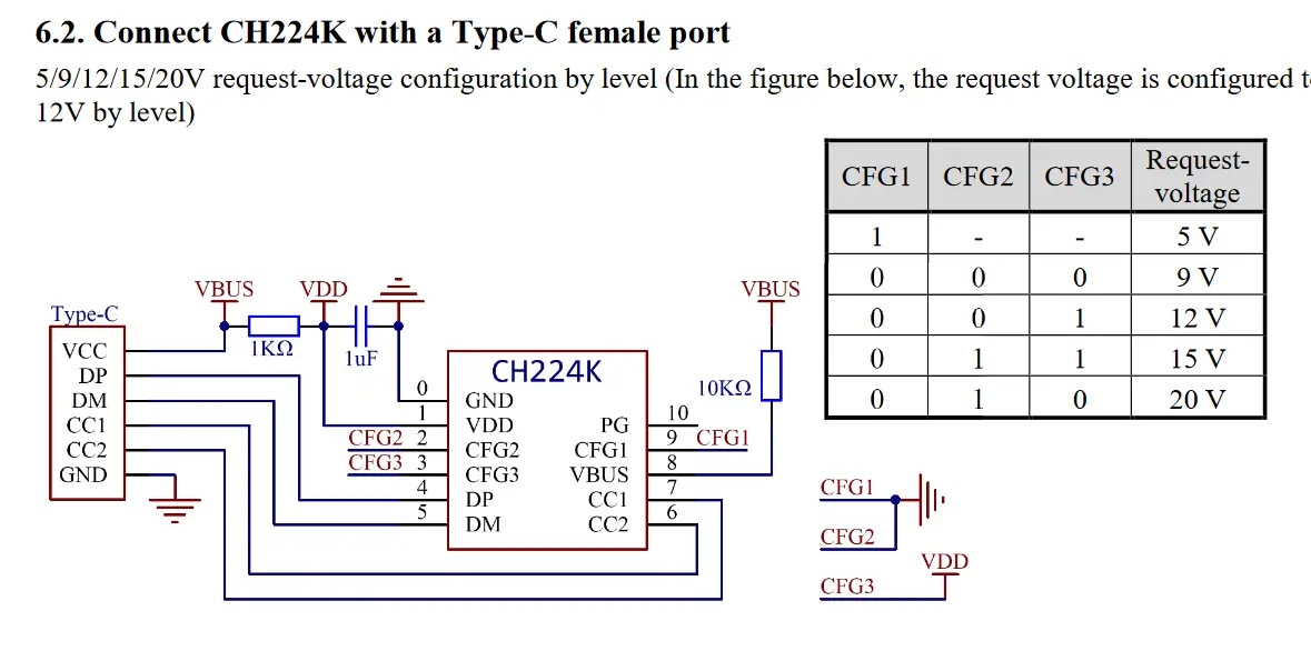
This is a fragment of the WCH CH224K documentation linked above. As you can see in this configuration mode one can adjust the resistance of the given pins to request different voltage levels.
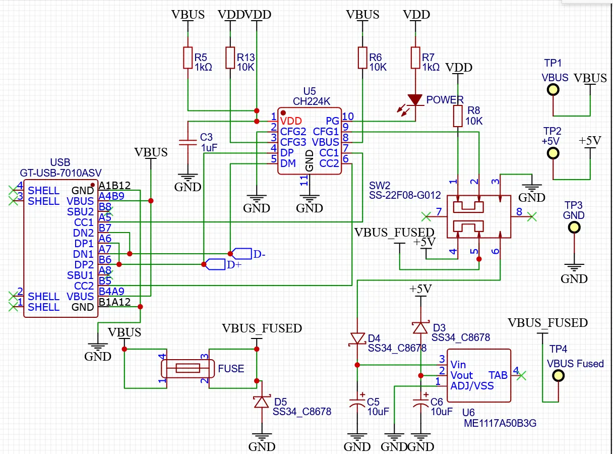
There’s a lot going on here but you can see the USB C part connected here to the WCH CH224K in a similar way to the datasheet. I’m relying on the fact the CH224K returns 5V if CFG1 is set to allow the switch to configure either 5V or 12V. For the 5V state I have CFG1 and CFG3 configured (the CFG1 pulled up to VDD sets this state regardless of the other pin state). In this way when 12V is selected CFG1 is pulled to GND causing the configuration for that level to work per the datasheet. The rest is straightforward and reflects the datasheet values. For the power on LED I opted for a 1K resistor emulating the choice by Stefan Wagner in his CH224K PD board.
Next, in the bottom left of the schematic fragment above you can see the VBUS input fused. This fused input is then connected to the switch either fed directly as 5V (in the 5V configuration) or via the 5V linear regulator.
In this way the D1 Mini is powered at 5V while still providing the fused VBUS at the selected voltage.
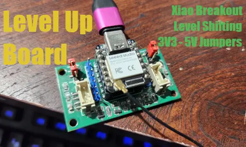
Level shifting
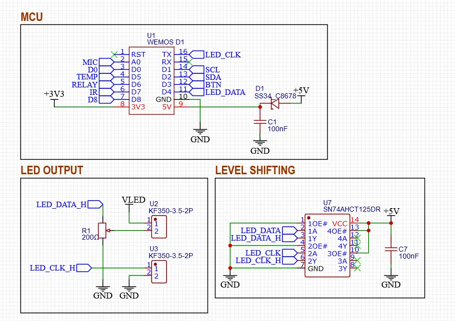
I’ve included the microcontroller here in the fragment to help further highlight its use and that of the level shifter. As you can see from the setup here the level shifter is powered from the 5V line and the output enable pins 1 and 2 are pulled to GND enabling them. The input sides for each of those is connected to the microcontroller and the output is then connected with the associated screw terminal on the high side.
Relay
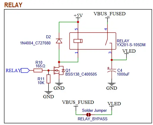
For the relay I have a low side switch using a n-channel mosfet to control the relay activation. There’s a flyback diode to handle the collapsing magnetic field.
Button
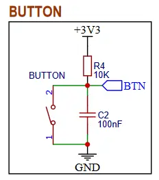
The button pin is pulled high via a 10K resistor. When the button is toggled it pulls the pin to GND. There’s a capacitor to debounce the signal.
More
There are additional elements of the schematic that can be viewed by inspecting it further such as the temperature 1-wire setup, the IR setup, i2c, the extra GPIO, and so on. They are fairly straightforward so I won’t be going into further depth here related to those.
Assembly
For assembly I built the circuit up and tested using my test points at various stages. To illustrate: one can add the USB, CH224K, switch and their passives and test the VBUS voltages to confirm the 5V and 12V toggle is working. Then the linear voltage regulator and its passives can be soldered to the board and the 5V test pin can further be utilized.
After this the remaining elements can be soldered. Primarily: headers for the D1 mini, the level shifter, the screw terminals, fuse holder, relay, button, IR receiver, and their passives. Given the microphone and oled have incorrect footprints in this revision they should likely be ignored. As of this point I have yet to test the temperature feature but it can also be soldered and additional grove ports can be installed for future extensibility (2 are on the i2c pins and 1 on extra GPIO surfaced from the D1 Mini).
Post Assembly
With the device assembled I suggest confirming the voltages are correctly reflected via the test points. When testing this power off the device prior to changing the voltage levels as the current setup has the VBUS directly connected when in the 5V toggle selection so when toggling from 12V it smokes the buffer prior to the CH224K updating to reflect the new requested voltage.
WLED configuration
In WLED you can further configure the device. A separate firmware install is required for the audioreactive and temperature usermods but the default install covers most of the main functionality provided by the board with a few settings changes.
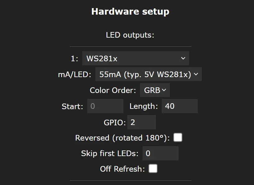
The first options are mostly related to the specific light strip you’re using so it will need to be configured based on your own needs. In my case I was using a WS2812 LED strip with 40 LEDs. The LED pin is GPIO 2 so I configured it here.
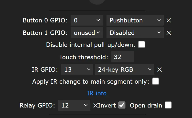
Here I’ve selected several GPIO for the various elements such as the button, IR receiver, and relay. These correspond to the values printed on the PCB itself for reference and ease of access. In addition I had several others listed but given the issues with the audioreactive build I was experiencing I am holding off there until I’ve redesigned this for an onboard esp32.
Example Usage
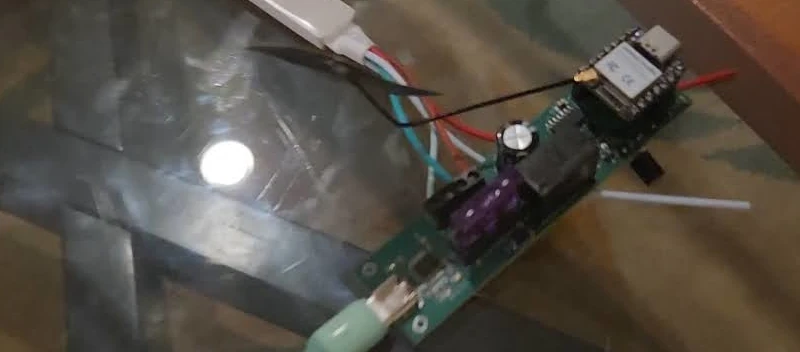
For the longest time I have had this aliexpress purchased dodecahedron infinity mirror. The one I purchased is no longer for sale but if you search aliexpress for “dodecahedron infinity mirror” you’ll likely find a comparable one. Some of the ads are misleading showing light strips with much high LED density so keep that in mind while shopping and look into reviews if you’re interested in grabbing one.
The LED device itself was rather simple it came with a small PCB with a USB input that powers the control board via two wires for VCC and GND. It then has a mic, the bluetooth antenna, and has three wires connected to a TRS cable which plugs into the female input for the dodecahedron. As such I simply snipped the three wires, trimmed them back a bit, and attached them to the screw terminals on the board for control. For a 5V LED strip one should ensure the LED toggle is set in that position prior to turning on the board to avoid damaging your strip.
Here I’m demonstrating using a 12V strip with the board just as a confirmation it works (I don’t have any LED projects currently requiring 12V but will in the future so wanted to be ready).
Next steps
I considered moving forward with custom firmware for the WLED install but given I’m likely to redesign the microcontroller setup here I’m going to save that for a future project once I’ve redesigned the board. For a first iteration I’m really happy with how it turned out and see it as a success. I’ll be using this for my dodecahedron infinity mirror going forward.
I also want to design a 3D printed enclosure for this board but I may wait for the future revision prior to doing so.