Unihiker (affiliate link) is a single board computer from DFRobot. The Unihiker runs a customized version of Debian and provides a “Pinpong” library to interface with the various GPIO. They also provide several sensor libraries they’re already ported.
For this project I’ll be controlling an LED ring, interfacing with the onboard buttons and light sensor, and using i2c to communicate with a SHT31 temperature and humidity sensor. The code for this project can be found here.
Background
I had the pleasure of trying out the DFRobot Unihiker as part of the Unihiker trial. Thank you DFRobot for sponsoring this project through the trial program!
I also recently picked up a Seeed Water Atomization module. Atomization modules are a key element to many interesting projects. For example, run the atomization module then shine a red LED and suddenly you have pretend flames (my child’s fake grill has this feature), use it with a pumpkin at halloween for spookey ambiance, or even just use it as a humidity generator for a grow room environment.
Function
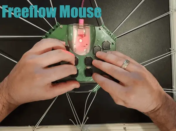
For the humidifier I opted to keep the functionality as simple as possible. I did persist the night light feature from my other Unihiker project. Please see the video for a detailed view of the device in use.
The unit is limited to:
- Enabling and disabling the humidify function in general
- Set point keeping for humidity level
- A touchscreen control unit for adjusting that set point and monitoring the state
In addition given I wanted to utilize the Unihiker more heavily and it felt like a useful “bonus” I’ve included on the display the Unihiker’s temperature and humidity as well as the end humidifier’s values. In this way you could keep the main unit by a nightstand and then the humidifier locked away nearby and check how the humidity is affected across the environment.
Careful: For the purposes of this demonstration many of the electronics are exposed. In a real deployment situation it would be advisable to seal the electronics in an enclosure and use cable grommets to prevent the humidity from affecting the components. Take heed and protect your electronics.
3D Printed Stand
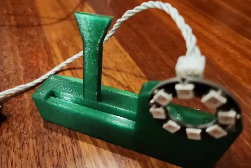
To aid with this project I created a simple 3D printed stand. It has a slot for the micro:bit connector for the Unihiker to slide down into and then a back piece to brace it. I didn’t require any supports to print it and used little infill. Seems to balance fine from my testing. There are 28 mm between the two holes for the LED ring and it uses m2 screws to connect.
Code
To set this up properly you will need to prepare both the Xiao and the Unihiker and their associated components.
Xiao ESP32S3
The Xiao ESP32S3 has a few elements hooked up here to get the entire project working.
The primary elements are as followed:
- Of course a Xiao ESP32S3
- A Grove Base for Xiao - optional but the HY2.0 4P connectors make setup fairly easy
- A Grove DHT11 Temperature and Humidity Sensor
- A Grove 4 Digit Display
- A Grove Water Atomization Module
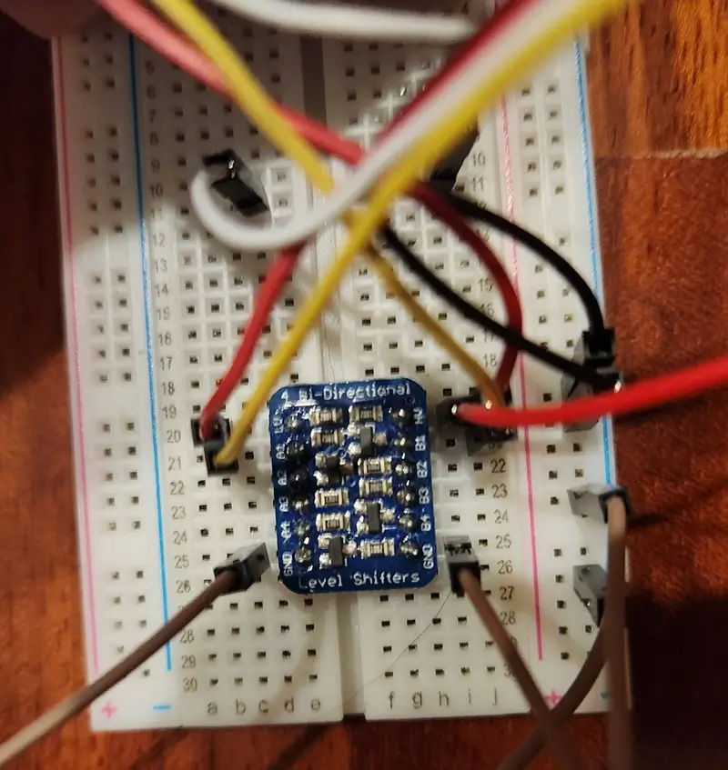
- A Bidirectional Level Shifter
Let’s get started with the setup, from here it’s actually not too bad outside of the level shifter and even that is fairly simple.
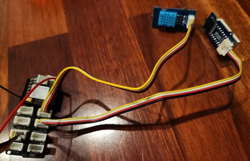
First connect the DHT11 via its Grove cable to the connector with the D0 as the outer pin. Given the DHT11 is a 1 wire interface you can see the Seeed folks set the other pin to NC meaning it’s not connected and can be ignored.
Next connect the 4 digit display. It’s connected to the Grove connector that shows D1 and D2 as the available signal pins. The D1 from the last connector is repeated here but it’s safe to use as we didn’t attach anything to D1 with the last connection per the NC.
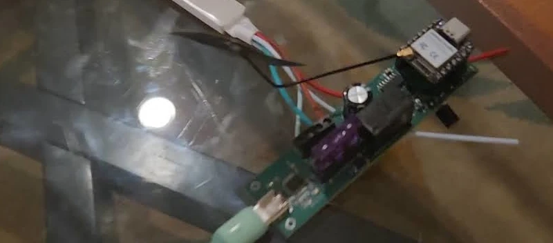
With this setup we only need to connect the atomization module. I find having a couple Grove to Dupont cables helps for this step as it allows me to still rely on the connectors for the end devices. For my own use I relied on two of these conversion cables along with some dupont male to male cables.
On the Xiao Grove Expansion board it’s possible to solder male or female pins to be able to use dupont cables directly from a pin. In this way I soldered female headers and used that male dupont cable to connect to the VBUS for the high voltage. From the VBUS pin I connected directly to HV pin on the level shifter.
With the HV setup you can then use the Grove to dupont cable connector, attach the red pin (3v3) to the LV pin on the level shifter. Attach the black pin to the common ground of your breadboard. Use dupont cables to then attach that common ground to the gnd inputs on the level shifter. Like the DHT11 the Atomization module only uses one signal wire so the additional wire can be plugged into an unused port on the breadboard to be kept out of the way. Connect the signal wire to one of the LV1-LV4 inputs. For the other Grove to dupont cable connect the NC signal wire to a random location, the signal wire to the corresponding HV# to the one you used (ie HV1 if you selected LV1), the red wire to the HV pin, and the black wire to the common GND.
In this way you will have setup the humidifier circuit. The screen is used for displaying the humidity, the DHT11 is used to return the humidity and temperature to ESPHome, and the atomization module is used for creating humidity.
Note: I’m not responsible if you destroy your electronics with humidity. I’d heavily suggest using an enclosure with a wire grommet and keeping your electronics away from moisture where possible.
For setup you’ll need to go through the normal ESPHome procedures for install. On my local machine I use the CLI to install the initial program and use my Home Assistant install to update OTA. Once you have ESPHome setup, use the associated yaml file from the repository to create the device. You’ll likely need to update it accordingly to get it working with your Home Assistant environment.
The ESPHome configuration file is available in the associated repository. You’ll want to make some changes to this depending upon your home assistant setup (setting up the encryption key and ota related values) but the gist of the file is in a state ready to use. I’ll describe some key elements here.
esphome:
  name: xiao-humidifier
  friendly_name: Xiao Humidifier
This is simply the name of the device.
# Uses the Xiao ESP32S3
esp32:
  board: esp32-s3-devkitc-1
  framework:
    type: arduino
This just selects the arduino framework and chooses the esp32s3 board.
# I have GPIO 7 which is pin D8 from the pinout as the humidifier signal
# See https://files.seeedstudio.com/wiki/SeeedStudio-XIAO-ESP32S3/img/2.jpg
switch:
  - platform: gpio
    pin: GPIO7
    name: "Humidifier"
As the comment mentions I’m using GPIO7 here / pin D8 as the enable pin for the atomization module.
# DHT sensor on GPIO1 / pin D0
sensor:
  - platform: dht
    pin: GPIO1
    temperature:
      name: "Xiao Temperature"
    humidity:
      name: "Xiao Humidity"
      id: xiao_humidity
    update_interval: 60s
DHT11 1 wire device on pin GPIO1 which is D0.
# Uses CLK and DIO pins GPIO2 / D1 and GPIO3 / D2
display:
  - platform: tm1637
    id: tm1637_display
    clk_pin: GPIO2
    dio_pin: GPIO3
    inverted: true
    length: 4
    # The logic here grabs the humidity using the xiao_humidity
    # name set above in the sensor: humidity: id: section
    # It then converts it to an integer and displays it
    lambda: |-
      if (id(xiao_humidity).has_state()) {
        char str[5];
        int humidity = static_cast<int>(id(xiao_humidity).state);
        snprintf(str, sizeof(str), "%02d", humidity);
        it.print(str);
      } else {
        it.print("----");
      }
I mistakenly said this was using i2c in the video but it’s using a two wire CLK and DIO interface for the TM1637 4 segment display. ESPHome makes it fairly easy to get up and running with the display. You can see I’m getting the value from the humidity sensor here and then displaying its contents on the display.
# This sets up the web server to allow the Unihiker access
# on the local wifi. I've setup an http basic username and
# password to add some level of security on the local network.
web_server:
  port: 80
  auth:
    username: !secret web_server_username
    password: !secret web_server_password
This is the important element for the purposes of this project. It allows the ESPHome device to surface a webserver which we’re connecting to and utilizing to update the device status.
DFRobot Unihiker
The Unihiker here is fairly straightforward to setup as it’s only relying on a few components.
I opted to use my stand with built in ringlight for this project. The STL for 3D printing is available on printables if interested. It’s a super simple stand for the Unihiker with a slot for the Micro:Bit connector, a backing piece to support the device which leaves the connectors free for use, and a ringlight for 8 LEDs for “night mode.”
Here I had only a minimal set of components:
- A DFRobot Unihiker
- A Grove SHT31 Temperature and Humidity Module
- A 8 LED ring with 28mm screw spacing (unfortunately not sure on my source for this one, just had on hand)
I soldered a SMD connector to the LED ring allowing me to connect it directly to the Unihiker. To do this I confirmed the pin orientation out of the Unihiker and positioned the connector such that the same pins would connect to the cable.
The SHT31 I connected via a Grove to dupont cable connection followed by a similar cable connecting back to the Unihiker port i2c port. Seeed and DFRobot use different pinouts for their i2c so pay attention to the signal wires to ensure the SDA and SCL are properly connected.
For installation you can follow the normal getting started procedures. For my own setup I used VSCode remote SSH extension they discuss allowing access to the filesystem. To install the script in my case I simply created a unihiker_humidifier.py script at the root. From there you can run programs, find the script, and run it to enable this logic. I like in a sense how this makes the Unihiker versatile for running all sorts of applications.
I’ll go into some detail about the code here so you can see how to further customize it. For this I’ll grabbing fragments of it to describe why it works the way it does. I suggest using the above link for the file itself versus copying this from here.
LIGHT_ENABLE_THRESHOLD = 300

# API User and password, set via ESPHome
BASIC_USERNAME = 'BASIC_USER'
BASIC_PASSWORD = 'BASIC_PASS'

# You'll need to provide the IP address of your ESPHome
# device on your local network. Giving it a static IP is
# helpful here.
BASE_URL = "http://192.168.2.103"

# These endpoints are provided by ESPHome
# https://esphome.io/web-api/index.html
HUMIDIFIER_ON_PATH = "/switch/humidifier/turn_on"
HUMIDIFIER_OFF_PATH = "/switch/humidifier/turn_off"
SENSOR_HUMIDITY_PATH = "/sensor/xiao_humidity"
At the top of the file there are several ENV variables. The first is the light enable threshold. It’s an arbitrary value you’ll want to configure for the point at which the light sensor should enable the LEDs. The default may be a bit low here but I wanted to simulate the lighting conditions so went with this value.
The BASE URL is the local network URL for your ESPHome device. If you only have the hostname of the device you can enter your terminal and find it via ping.
For example:
ping xiao-humidifier.wild

PING xiao-humidifier.wild (192.168.2.103) 56(84) bytes of data.
64 bytes from 192.168.2.103 (192.168.2.103): icmp_seq=1 ttl=254 time=253 ms
^C
--- xiao-humidifier.wild ping statistics ---
2 packets transmitted, 1 received, 50% packet loss, time 1001ms
rtt min/avg/max/mdev = 253.172/253.172/253.172/0.000 ms
I suggest setting a static IP for the device on your local network and then updating it as needed.
NEOPIXEL_PIN = Pin(22)
PIXELS_NUM = 8
neopixel = NeoPixel(NEOPIXEL_PIN, PIXELS_NUM)
The logic here uses Pin 22 as the LED ring control pin.
This is the same nightlight functionality I used in my scale.
LIGHT_ENABLE_THRESHOLD = 300
Board("UNIHIKER").begin()
lightEnabled = None

def handleNightMode():
    global lightEnabled
    lightValue = light.read()
    if 0 <= lightValue < LIGHT_ENABLE_THRESHOLD:
        lightEnabled = True
        for i in range(PIXELS_NUM):
            neopixel[i] = (20, 20, 20)
    elif lightEnabled:
        lightEnabled = False
        for i in range(PIXELS_NUM):
            neopixel[i] = (0, 0, 0)

while True:
    handleNighteMode()
The humidifier control unit is rather simple. I initialize the GUI and its elements:
gui = GUI()

# Page header
gui.draw_text(text="Humidifier", x=45, y=15, font_size=25, color="teal")

# Draw initial values on GUI
current_state = gui.draw_text(text="OFF", x=20, y=70, font_size=9, color="teal")

gui.draw_text(text="Xiao Humidity", x=20, y=170, font_size=9, color="teal")
gui.draw_text(text="Device Humidity and Temperature", x=20, y=290, font_size=9, color="teal")

# These draw the humidity and temperature text on the screen
# That text is then updated during the program loop
humidity_text = gui.draw_digit(x=180, y=140, text=str(humidity_set_point), origin="center", color="blue", font_size=50)
current_humidity_text = gui.draw_digit(x=50, y=140, text="0", origin="center", color="blue", font_size=50)
unihiker_humidity_text = gui.draw_digit(x=50, y=260, text="0", origin="center", color="red", font_size=40)
unihiker_temperature_text = gui.draw_digit(x=180, y=260, text="0F", origin="center", color="red", font_size=40)

# Add up and down buttons for humidity set point adjustment
gui.add_button(x=180, y=80, w=50, h=30, text="Up", origin='center', onclick=increase_humidity_set_point)
gui.add_button(x=180, y=190, w=50, h=30, text="Down", origin='center', onclick=decrease_humidity_set_point)
This pretty much is just plain GUI related setup work. You can see from the x and y locations it’s fairly easy to setup a base GUI to work from.
I added some helper methods to configure the humidity (relying on the global variable to set the current state):
def increase_humidity_set_point():
    global humidity_set_point
    humidity_set_point = min(100, humidity_set_point + 1)
    humidity_text.config(text=str(humidity_set_point))

def decrease_humidity_set_point():
    global humidity_set_point
    humidity_set_point = max(0, humidity_set_point - 1)
    humidity_text.config(text=str(humidity_set_point))

def get_current_humidity():
    response = requests.get(f"{BASE_URL}{SENSOR_HUMIDITY_PATH}", auth=(BASIC_USERNAME, BASIC_PASSWORD))
    data = response.json()
    return data["value"]

def set_humidifier_state(state):
    url = f"{BASE_URL}{HUMIDIFIER_ON_PATH}" if state else f"{BASE_URL}{HUMIDIFIER_OFF_PATH}"
    requests.post(url, auth=(BASIC_USERNAME, BASIC_PASSWORD))
And then in the loop I handle the night mode logic, grab the humidity values, update the GUI to reflect it, and handle the button pressing events:
while True:
    handleNightMode()

    xiao_humidity = get_current_humidity()
    current_temperature = int(sensor.temp_f())
    current_humidity = int(sensor.humidity())

    current_humidity_text.config(text=str(xiao_humidity))
    unihiker_humidity_text.config(text=str(current_humidity))
    unihiker_temperature_text.config(text=f"{current_temperature}F")

    if button_a.is_pressed():
        current_state.config(text="ON")
        humidifier_enabled = True
    elif button_b.is_pressed():
        current_state.config(text="OFF")
        humidifier_enabled = False
        set_humidifier_state(False)

    if humidifier_enabled:
        if xiao_humidity < humidity_set_point:
            set_humidifier_state(True)
        else:
            set_humidifier_state(False)

    time.sleep(0.1)