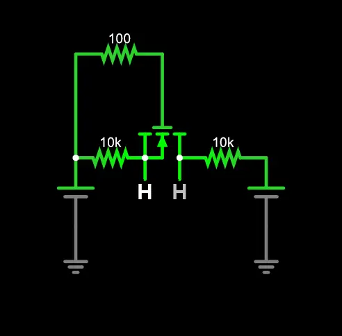
This is a simple DIY project involving a bidirectional level shifter. These are fairly cheap boards that use n-channel mosfets (BSS138) to shift a signal up and down.
You can test the general idea behind the circuit here (falstad). The two circuits shown are identical in that link aside from a change to the input and output to allow for both directions to be tested.
I believe this works by (my understanding came from this great reddit answer):
- When the LV side is LOW it causes a Vgs of 3V3 which is more than the 1V5 needed to fully activate the mosfet. Once activated it causes current to flow and pulls the HV side down as well. When it’s high the Vgs is 0 so current doesn’t conduct and with the pull up resistors both sides are kept at their respected voltage.
- When the HV side is brought LOW it causes the diode to become reverse biased (from what I’ve gathered) which in turn allows the body diode to allow current through it. This in turn causes the source voltage to drop in turn causing the Vgs to climb until the mosfet is fully activated and the LV side is also brought fully to LOW.
Purpose
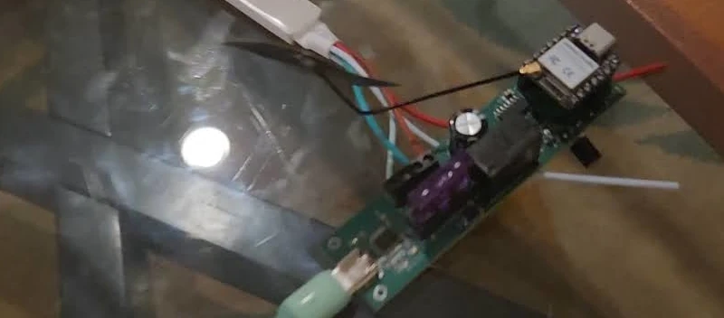
A level shifter allows your microcontroller which tend to use 3V3 to interface with actuators and sensors that require a higher voltage. Sometimes a sensor may work with the lower voltage but just isn’t as accurate other times it may not run at all at the voltage level if it’s below a certain point. For example the Seeed Water Atomization module operates at 5V putting this module out of reach for most microcontrollers without a level shifter in the mix.
Using a Bidirectional Level Shifter
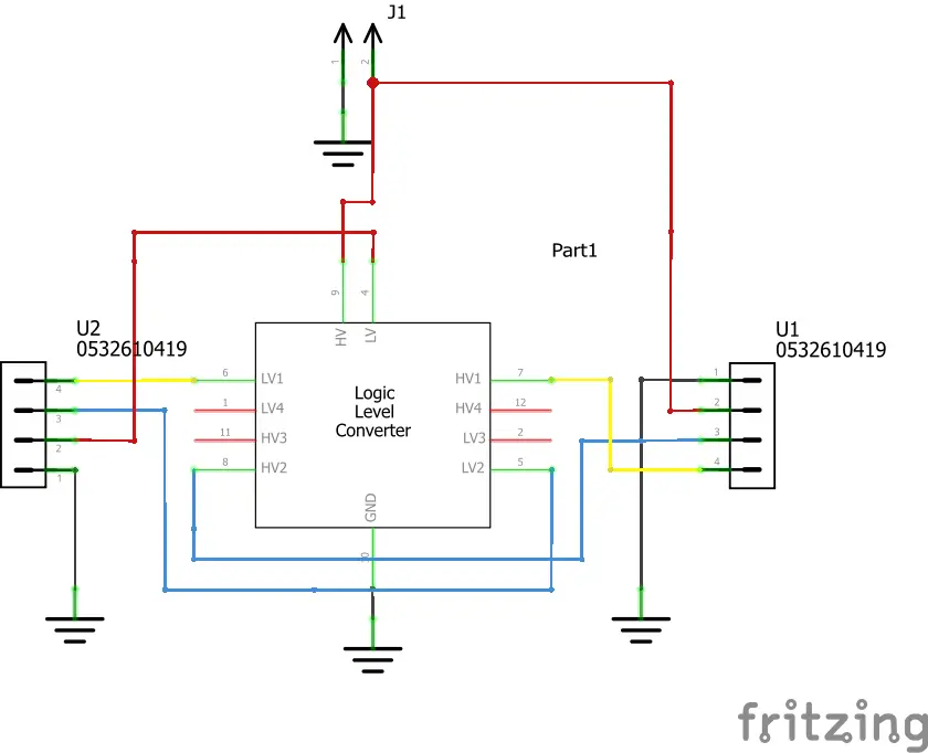
Bidirectional level shifters are fairly easy to use but quickly make a project a mess given the need for several wires. At their simplest setup you place wires for each signal line you want to shift to a LV# pin on the shifter. Their corresponding HV# pin is then connected to whatever device you wanted to utilize. The LV pin is associated with the lower voltage while the HV pin is associated with the higher voltage. In addition a common ground must be used between the two voltage sources.
Often times MCUs will provide a pin for the VBUS line which comes from the USB. One could use this as the HV side and have the LV side be the 3V3 from the microcontroller to level shift up to that level. If you need a lot of current a separate 5V voltage source would be ideal over using this though as your microcontroller will also require current to operate and USB 2.0 only allows for up to 500mA. USB PD allows for up to 3A@5V so there are a lot more possibilities when you bring something like a CH224K from WCH into the mix to negotiate for USB PD.
Grove Level Shifting Board
For this project I put together a little Grove level shifting board that allows for no solder level shifting. It’s just a circuit that uses the Adafruit Bidirectional Level shifter, 2 HY 2.0 4P connectors, a pin for the HV level, and then some wires to get it all in place.
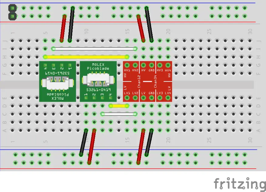
For this setup it’s really basic you just want to make sure that you have the HY 2.0 4P connectors setup to the correct LV# and HV# pins on each side. The rest is really just routing the wires correctly per the above.
The end result is you can connect a Grove cable on one end with 3V3 and 3V3 signals and on the other end get 5V and 5V signals out another Grove cable with the help of one dupont cable to the 5V HV. This in turn ends up giving you a much smaller setup in terms of cables for shifting.
Testing Code Used in the Video
// Initialize the Grove LED Button (D6, D7 signals)
const int ledPin = D7;
const int buttonPin = D6;
// Atomization module is on D0
const int enablePin = D0;

// Initial state in the off position
bool enabled = false;
bool buttonState = false;
bool lastButtonState = false;

void setup() {
  // The three pins are setup with the button as an input and others as output
  pinMode(ledPin, OUTPUT);
  pinMode(enablePin, OUTPUT);
  pinMode(buttonPin, INPUT);

  // LED and atomization enable are pulled low to set initial state
  digitalWrite(ledPin, LOW);
  digitalWrite(enablePin, LOW);
}

void loop() {
  // Check if button has been driven low
  buttonState = digitalRead(buttonPin) == LOW;

  // If the button has changed its state
  if (buttonState && !lastButtonState) {
    // Toggle
    enabled = !enabled;

    digitalWrite(ledPin, enabled ? HIGH : LOW);
    digitalWrite(enablePin, enabled ? HIGH : LOW);
  }

  lastButtonState = buttonState;

  delay(50);
}
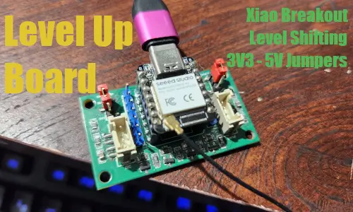
My Level Up Xiao Board
My little level up Xiao board is coming soon!
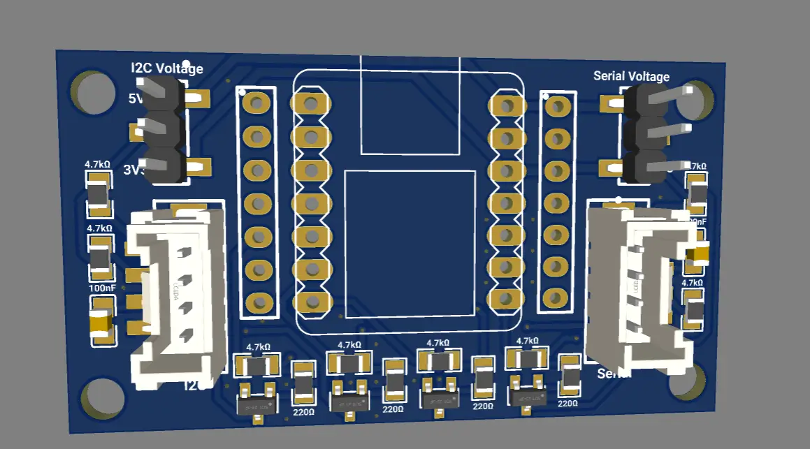
I’ve ordered it from PCBWay (thanks Serene!) and it should be coming in the next week or so for testing.
I’ll go into more detail once the board arrives but I wanted to take the elements of the level shifter and make it a permanent feature of my helper board.
I’m a big fan of Seeed Studio Grove Base for XIAO (affiliate link). The board makes it very easy to get up and running with a project with little to no soldering. It has pins for an extra row of the main headers allowing for dupont wires to connect to any of those, comes with a battery bonding pad and charging circuit allowing for use with the Xiao without onboard battery ICs (RP2040 and SAMD21), and has an optional flash bonding pad allowing for expandability. In addition to those features it has a tons of HY 2.0 4P connectors allowing you to connect Grove modules easily. Given that I wanted to create a board that used the elements I relied on the most with it.
For the first iteration of my board I decided:
- Xiao pinout allowing for use with the Seeed’s Xiao line of boards (affiliate link) and Adafruit’s QT Py
- I wanted at least two Grove inputs (HY 2.0 4P) with one as I2C and the other UART
- I wanted the ability to optionally set either to 5V or have it still default to 3V3
- Given the I2C bus is easily expanded with a Grove I2C Hub (affiliate link) I didn’t want to overload the board with I2C ports
- Allow for expandability via the matching pins to the Xiao pinout