For this project I’m utilizing Seeed Vision Module V2 as the control mechanism for the Adeept Omni-directional Mecanum Wheels car kit. I’ve created a Printables model that can be downloaded and printed to attach the sensor to the device.
Prerequisites
For more information about the robot car kit you can check my article on the lessons from the Adeept tutorials with the car.
Background
For this project I’ve created Arduino libraries to control the car and its features. I did this such that I could use the SSCMA library from Seeed Studio. I contemplated porting it to CircuitPython but in the end decided this would be a good learning opportunity.
Code
The code can be found here. There are three directories that are self contained with the associated Arduino code. I included my test projects along with the final car control logic in that repository.
This code is written in C++ for Arduino. You’ll need the Espressif core board package installed with Arduino. Banana Pi does not include a board specifically for this in the board package so you need to use the “ESP32S3 Dev Module” instead. This also means you’ll need to use the GPIO pins from the ESP32S3 directly versus the silkscreen pinout from the Banana Pi PicoW S3.
| Silkscreen GPIO | ESP32S3 GPIO |
|---|---|
| 0 / TX | 43 |
| 1 / RX | 44 |
| 2 | 47 |
| 3 | 17 |
| 4 | 15 |
| 5 | 13 |
| 6 | 12 |
| 7 | 14 |
| 8 | 18 |
| 9 | 16 |
| 10 | 21 |
| 11 | 38 |
| 12 | 39 |
| 13 | 40 |
| 14 | 41 |
| 15 | 42 |
| 16 | 1 |
| 17 | 2 |
| 18 | 3 |
| 19 | 4 |
| 20 / SDA | 5 |
| 21 / SCL | 6 |
| 22 | 7 |
| 26 | 8 |
| 27 | 9 |
| 28 | 10 |
| run | rst |
For getting Arduino configured you can see the guide from Espressif. The short of it is you need to add the board support package located at https://espressif.github.io/arduino-esp32/package_esp32_index.json and then in the boards tab type “Espressif” to find and install.
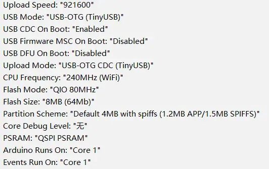
For the configuration options in Arduino I relied on the Banana Pi Leaf S3 related documentation which worked in this case as well.
MotorControlTest
Initially I was thinking of using the ultrasonic sensor to detect the range of the person in front of the vehicle to aid with the distance tracking. As such I added support for it in this example but I didn’t end up using it in the final code.
I’ll hit some of the elements here to give some information:
#define SDA_PIN 5
#define SCL_PIN 6
#define NUM_LEDS 4
#define DATA_PIN 38
#define BUZZER_PIN 8

// Define trigger pin as 17 and echo pin as 47
Ultrasonic ultrasonic(17, 47);
Adafruit_NeoPixel strip = Adafruit_NeoPixel(NUM_LEDS, DATA_PIN, NEO_GRB + NEO_KHZ800);

ServoControl servoControl(14);
MotorControl motorControl;
I2C_LCD lcd(0x27);
The logic initializes and configures the different elements using their GPIO pins (versus the silkscreen).
void playTone(int pin, int frequency, int duration) {
    int period = 1000000L / frequency;
    int pulse = period / 2;
    for (long i = 0; i < duration * 1000L; i += period) {
        digitalWrite(pin, HIGH);
        delayMicroseconds(pulse);
        digitalWrite(pin, LOW);
        delayMicroseconds(pulse);
    }
}

void playAlertSound() {
    int frequencies[] = {370, 415, 330, 233, 311};
    int durations[] = {50, 50, 50, 50, 300};

    for (int i = 0; i < 5; i++) {
        playTone(BUZZER_PIN, frequencies[i], durations[i]);
    }
    digitalWrite(BUZZER_PIN, LOW);
}
There’s logic which attempts to play a sound on alert here. I tried to make it sound similar to the Metal Gear Solid alert noise but it was hard with a buzzer.
Inside the setup method:
    delay(5000);
    Serial.begin(9600);

    pinMode(BUZZER_PIN, OUTPUT);

    strip.begin();
    strip.show();
    for (int i = 0; i < NUM_LEDS; i++) {
        strip.setPixelColor(i, strip.Color(255, 0, 0));
    }
    strip.show();

    Wire.begin(SDA_PIN, SCL_PIN);
    lcd.begin(16, 2);

    lcd.setCursor(0, 0);
    lcd.print("Starting...");

    // Testing alert sound
    playAlertSound();
The logic is pretty straightforward first initializing the LED strip to red, it configures i2c, and the LCD with an initial message.
    delay(500);
    // Test servo: sweep from -90 to 90 degrees and back
    for (int angle = -90; angle <= 90; angle += 10) {
        Serial.print("Setting servo to ");
        Serial.print(angle);
        Serial.println(" degrees");
        lcd.setCursor(0, 1);
        lcd.print("Servo: ");
        lcd.print(angle);
        servoControl.setAngle(angle);
        delay(500);
        lcd.clear();
    }

    servoControl.setAngle(0);
The servo does a sweep from side. YOu can see it does it in 10 degree increments.
    for (int i = 0; i < NUM_LEDS; i++) {
        strip.setPixelColor(i, strip.Color(0, 255, 0));
    }
    strip.show();
Given the LEDs are RGB this sets them all to green. The array is 0-indexed and as such it updates all four LEDs by looping over them.
    // Test each motor in each direction for one second
    Serial.println("Testing forward");
    lcd.setCursor(0, 1);
    lcd.print("Forward ");
    motorControl.moveCar(MOVE, FORWARD, 50);
    delay(1000);
    motorControl.stopAllMotors();
    lcd.clear();
...
Each of the directions is tested here. It’s useful to compare the direction of the wheels to mecanum car directional graphics while testing.
    for (int i = 0; i < NUM_LEDS; i++) {
        strip.setPixelColor(i, strip.Color(0, 0, 255));
    }
    strip.show();
Finally the color is set to blue.
void loop() {
    // Get distance from ultrasonic sensor
    float distance = ultrasonic.getDistance();
    Serial.print("Distance: ");
    Serial.print(distance);
    Serial.println(" cm");

    // Display distance on LCD
    lcd.setCursor(0, 0);
    lcd.print("Distance: ");
    lcd.print(distance);
    lcd.print(" cm");

    delay(1000);
}
The loop is straightforward and just gets the distance to the item detected by the ultrasonic distance sensor and displays it on the LCD.
The motors code can be inspected to see how all that works. In short it’s using the mcpwm library for controlling the motors here.
VisionSensorTest
The vision sensor test is in this directory. For the most part the initialization is similar to the last test. The big difference is the presence of the SSCMA library for interfacing with the Seeed vision sensor v2 module.
As we’re already using the i2c bus for the LCD we don’t need to configure anything else there. I’m going to focus on the loop in particular for this example.
void loop() {
    static bool personDetected = false;
    static bool alertGiven = false;
    static unsigned long lastDetectionTime = 0;

    if (!Infer.invoke()) {
        if (Infer.boxes().size() > 0) {
            personDetected = true;
            lastDetectionTime = millis();

            if (!alertGiven) {
                // Red when person is detected
                setLEDColor(255, 0, 0);
                playAlertSound();
                alertGiven = true;
            }

            int personX = Infer.boxes()[0].x;
            int personWidth = Infer.boxes()[0].w;

            lcd.clear();
            lcd.setCursor(0, 0);
            lcd.print("Width: ");
            lcd.print(personWidth);
            lcd.setCursor(0, 1);
            lcd.print("X: ");
            lcd.print(personX);

        } else {
            if (personDetected && (millis() - lastDetectionTime > 10000)) {
                setLEDColor(0, 0, 255);
                personDetected = false;
                alertGiven = false;
            }
        }
    }
}
The logic is setup to invoke the model. After it invokes it gets back the bounding boxes and takes the first returned result, grabs the x value and the width of the box, and then outputs it on the LCD. If this was a new detection it sets the LEDs red and plays the alert noise. If a face has not been detected for 10 seconds it sets the LEDs to blue and returns back to “scanning mode.”
MotorControl
This is the main project and brings those elements together. I won’t repeat the above here but will go into the control code:
int personX = Infer.boxes()[0].x;
int personWidth = Infer.boxes()[0].w;

bool moveLeft = personX < 80;
bool moveRight = personX > 140;
bool moveForward = personWidth < 45;
bool moveBackward = personWidth > 50;
bool turnLeft = personX < 40;
bool turnRight = personX > 180;
The servo control logic shown in the SSCMA examples was a great starting point to learn how to use the API response here. I did some experiments with my face at various distances to determine the size of the box when I was close and further away. The x value here is located at the center of the bounding box and the w value is the width of the box.
I then used the above variables to control the car’s actual movement based on their state.
if (turnLeft) {
    Serial.println("Turn Left");
    motorControl.moveCar(MOVE, TURN_LEFT, 50);
    delay(100);
    motorControl.stopAllMotors();
    lcd.print("Turn Left");
} else if (turnRight) {
    Serial.println("Turn right");
    motorControl.moveCar(MOVE, TURN_RIGHT, 50);
    delay(100);
    motorControl.stopAllMotors();
    lcd.print("Turn Right");
Turning moves fairly quickly (in retrospect perhaps I should have used a smaller value for the speed) which can be a problem when using the face sensing so I opted to only turn for 100ms at a time.
} else if (moveForward) {
    lcd.print("Action: Moving");
    lcd.setCursor(0, 1);
    if (moveLeft) {
        Serial.println("Moving left forward");
        motorControl.moveCar(MOVE, LEFT_FORWARD, 50);
        lcd.print("Left Forward");
    } else if (moveRight) {
        Serial.println("Moving right forward");
        motorControl.moveCar(MOVE, RIGHT_FORWARD, 50);
        lcd.print("Right Forward");
    } else {
        Serial.println("Moving forward");
        motorControl.moveCar(MOVE, FORWARD, 50);
        lcd.print("Forward");
    }
For the forward and backward (not shown here) movement the logic determines if it should also move left or right and if so moves in that direction.
} else if (moveLeft) {
    lcd.print("Action: Moving");
    lcd.setCursor(0, 1);
    Serial.println("Moving left");
    motorControl.moveCar(MOVE, LEFT, 50);
    lcd.print("Left");
} else if (moveRight) {
    lcd.print("Action: Moving");
    lcd.setCursor(0, 1);
    Serial.println("Moving right");
    motorControl.moveCar(MOVE, RIGHT, 50);
    lcd.print("Right");
} else {
    Serial.println("Stopping all motors");
    motorControl.stopAllMotors();
    lcd.print("Action: Stopped");
    lcd.setCursor(0, 1);
}
If there’s no movement forward or backwards it strafes in that direction and if there’s no movement at all it stops the motors.
Summary
It was a fun project to work on that I learned quite a bit with. Up until this moment I haven’t spent much time with robotic programming. I’ll definitely use what I’ve gained here for projects in the future.
The Seeed Vision Sensor V2 has also been great. I’m a fan of how easy it is to program and train models for. I have a couple other projects I’ll be posting in the next few days.