This project utilizes the Seeed Vision AI V2 sensor in an enclosed manner with use of a solar panel to ensure the device stays powered. For this project I used the pretrained person sensor model with the goal of detecting my kids if they enter the pool area.
Model Setup
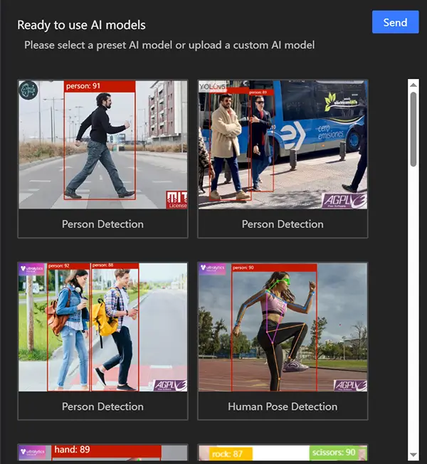
The first step is to get your vision AI sensor configured for the model. After some testing I found the Swift YOLO model effective for person detection.
The process to get setup is fairly straightforward:
- Using Chrome or Microsoft Edge Visit the SenseCraft Web Toolkit
- Connect to your device via the “Connect” button
- A web serial popup will appear allowing you to connect to your device
- Select a model from the available and send to the device
In the case of a self trained model there are additional steps required as you need to train it using the SSCMA library and associated notebooks (at the time of this writing). For this project though we’re using a built in model so with this step we’re done.
Telegram Setup
For the telegram setup you can refer to the Seeed Wiki article on the topic. I’ll go over the general steps here.
- Contact the BotFather sending the message
/newbotto initiate the bot creation process - Respond to the messages from the BotFather giving your bot a name and username
- After this the bot will respond with a token you can use for interfacing with the API
- Adding this bot to a group will associate a chat id with your user and the bot (until this step is taken the response will not contain a chat id)
- Hitting the endpoint
https://api.telegram.org/bot{Token}/getUpdatesafter replacing the{Token}with your token will return a payload that includes your chat id - After you’ve received this chat id you can subsequently send messages to the bot via the
/sendMessageendpoint
With cURL you can send a message directly to the bot via:
curl https://api.telegram.org/bot{Token}/sendMessage -H 'Content-Type: application/json' -X POST --data '{"chat_id": 7216726720, "text":"Test Message"}'
Components / Circuit Setup
I’ve used the following components with this setup (affiliate links):
- DIY Level Shifter
- Grove Vision AI V2 Sensor
- Xiao ESP32C
- FOV Camera for RP
- 90 Degree USB Connector
- Enclosure
- Grove Shield for Xiao
- Grove LED Bar
- Solar Panel
- Buzzer
- Lipo Rider Pro
It’s a mostly no solder setup (aside from the DIY Level Shifter). I’ll walk through the connections here to help make the setup easier to follow. I suggest VHB tape from 3M for mounting as it holds well.
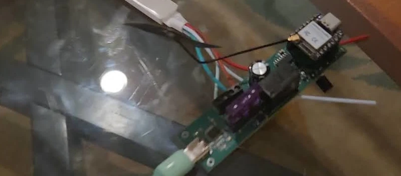
- First take the Lipo Rider Pro and position it such that there’s enough room for the 90 degree connector, connect the 90 degree connector
- Attach the solar panel via its connector
- Attach a lithium ion battery to its connector
- Attach the Xiao ESP32C3 to the Grove Shield and break off the extra HY 2.0 4P connectors (for this enclosure I could not fit the full shield)
- With the Xiao ESP32C3 now connected attach it to the 90 degree connector via the USB-C connection
- Connect the buzzer to the A1 A0 grove connector via a Grove cable (A1 is not used in this case as the Buzzer only uses the 4th pin)
- Connect the LED bar to the A2 A1 grove connector via a Grove cable (both pins are used here)
- You will need to level shift for the Grove Vision AI V2 (it seems to work with 3V3 but the wiki states it only takes 5V so likely not a good idea – the Grove connection leads to a 3V3 regulator and expects 5V from the schematic)
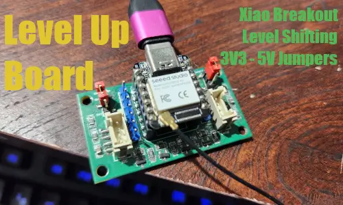
- For the level shifting connect SDA and SCL to the LV#s side of a level shifter, connect the LV to 3V3, GND to GND. On the HV side connect the HV to the 5V / VBUS from the Grove Shield extra pins, then connect the corresponding SDA and SCL wires leading to the Grove Vision AI V2 along with the GND wire. To make this process simpler I setup a DIY inline level shifter circuit I described in another article. I also designed a Xiao Level Shifting base board that’s on the way – hoping it simplifies future projects.
- With the connections in place use the VHB tape to prevent movement in the enclosure for most of the parts and electrical tape to hold the LED bar, solar panel, and camera to the roof.
So yeah it sounds mighty complicated but it really isn’t it’s just of Grove cables connecting various sensors to the device. I really don’t like soldering components in general (outside of individual pieces) as it limits future project reuse so I love situations like this where you can rely on the existing expansion boards to piece together a full device.
Given this project is relying on the Grove cables I’m not going to include a Fritzing image of the circuit. The level shifter circuit used is included in my other article which delves into how it works and provides a link to Falstad’s circuit tester where you can try it in action (really appreciate that site).
Code
For the code you’ll first want to setup Arduino for use with the Espressif boards. To do this you’ll need to:
- Press
Filefrom the menu bar and pressPreferencesfrom the list - Near the bottom of the screen you’ll see an area for additional board management URLs to be added. Here you’ll want to add
https://espressif.github.io/arduino-esp32/package_esp32_index.jsonto the comma separated list (it may be blank if this is the first non-Arduino board you’re configuring) - After installing go to the boards submenu from the left-hand side bar selection menu
- Type in “Espressif” in the search bar
- You’ll see a
esp32board option, install this to setup the associated esp-tool tooling and related boards - In the code screen pull down the board select and type in “Xiao ESP32C3” it should return the associated board
- For the libraries you’ll need to add the 1.0.1 version of the LED Bar from GitHub as it hasn’t been published at this time
- In addition the SSCMA library should be installed
The entire code for this example can be found with my gist. I’ll go over some of the associated code but it’s pretty simple.
// Threshold for detection
const int threshold = 70;
const int dataPin = D2;
const int clockPin = D1;
const int buzzerPin = D0;
Here I configured the associated pins for the LED bar, the buzzer’s pin, and the threshold needed to trigger the telegram alert.
SSCMA AI;
Grove_LED_Bar bar(dataPin, clockPin, 0, LED_BAR_10);
Creating the associated objects for interfacing and controlling the LED bar.
void setup() {
    AI.begin();
    Serial.begin(9600);
    WiFi.begin(ssid, password);
    while (WiFi.status() != WL_CONNECTED) {
      delay(1000);
      Serial.println("Connecting to WiFi...");
    }
    Serial.println("Connected");

    bar.begin();
    pinMode(buzzerPin, OUTPUT);  // Buzzer on D0
}
The setup logic connects to the WiFi, retries until it connects, and then associates the buzzer pin as an output.
Each iteration of the loop it resets the count of people detected and the highest confidence found.
After that:
  if (!AI.invoke()) {
    for (int i = 0; i < AI.boxes().size(); i++) {
        if (AI.boxes()[i].score > threshold) {
            peopleDetected++;
            if (AI.boxes()[i].score > highestConfidence) {
                highestConfidence = AI.boxes()[i].score;
            }
        }
    }
It invokes the model and if that was successful then it loops over the boxes returned counting those that had a score higher than the threshold set and also what the highest confidence seen was.
    // Update LED bar
    int ledsToLight = map(highestConfidence, 0, 100, 0, 10);
    bar.setLevel(ledsToLight);
Here it uses this highest confidence to light up the LED bar. As I set the alerting confidence to 70% it will show 7 to 10 (likely never 10 though) lights depending upon the score. One could modify the above loop to move the confidence logic outside of the threshold check to view it from 0 to 10 but for my purposes I only wanted it showing when it alerted.
    if (peopleDetected > 0) {
        Serial.println("People detected");
        if (WiFi.status() == WL_CONNECTED) {
            String message = "People Detected: " + String(peopleDetected) + "\Confidence: " + String(highestConfidence);
            sendMessage(message);
        }

        // Trigger buzzer
        digitalWrite(buzzerPin, HIGH);
        delay(1000);  // Buzzer delay
        digitalWrite(buzzerPin, LOW);
    }
If people were detected in this iteration of the loop it then sends a message to telegram to trigger the alert.
void sendMessage(String text) {
  String url = "https://api.telegram.org/bot" + botToken + "/sendMessage";
  String payload = "{\"chat_id\":\"" + chatId + "\",\"text\":\"" + text + "\"}";

  HTTPClient http;
  http.begin(url);
  http.addHeader("Content-Type", "application/json");

  int statusCode = http.POST(payload);
  if (statusCode == 200) {
    Serial.println("Message sent successfully!");
  } else {
    Serial.println("Failed to send message.");
  }
  http.end();
}
Here the logic puts everything together from the BotFather. Using the token it provided earlier you can hit the /sendMessage API with the payload containing the chatId and associated text for the message. This sends the message to the end user via that chat.
Final Thoughts
In general I found this approach to work well; the components fit within the case, I’m able to get 5V from the lipo rider pro which I need for the Vision AI V2 sensor, and the telegram approach is effective for community.