In this project I’ll discuss my Level Up Board for level shifting Xiao form factor projects. This project is a board I designed to replace my earlier inline DIY level shifter I’ve used for various projects.
Link to board project: pcbway
Project Sponsorship
At this time I want to thank PCBWay for sponsoring this project by providing the PCBs. I’m grateful they put faith in my project and gave me this opportunity. Their website can be accessed for more details about their product line. I like how easy it was to go from my gerber to the shipped product and the boards I received seem of high quality. Their capabilities page has a lot information about what they can help you with. PCBWay really does make it easy to get started, build professional PCBs for your project, and see your ideas come to fruition. Love it.
Why make this board?
I have three uses for this board:
- If I want to use UART serial communication with a 5V board I need to level shift for the signals and power to avoid hurting the Xiao with its 3V3 pins
- There are some 5V only i2c devices such as the Seeed Vision AI sensor v2 (you can attach the Xiao directly to the board to get around this but my projects usually use multiple sensors so I prefer attaching it via a cable)
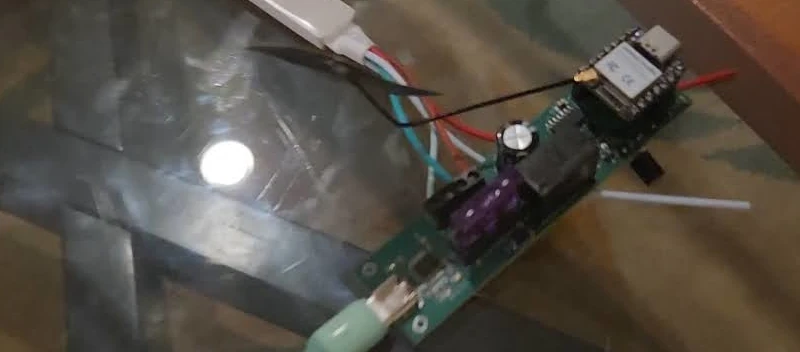
- There are some actuators that require 5V like the Seeed Water Atomization module
In the past I took care of this by assembling an inline DIY level shifter. It works well but I prefer simplicity with enclosures and it makes things a bit more difficult as each DIY board has slightly different dimensions.
Schematic
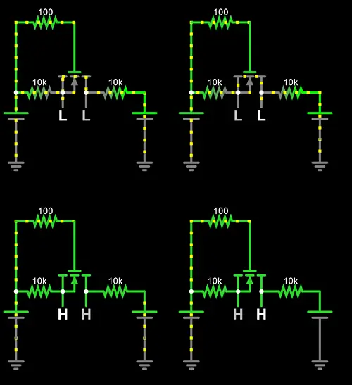
So first I want to describe the logic here and give an example circuit to play around with it. This falstad circuit is the one I put together to verify my assumptions prior to ordering the PCB. With this setup you can see four different circuits. The top two are 3V3 to 5V which is a fairly normal setup for level shifting while the bottom two are 3V3 to 3V3 so demonstrating the behavior when not level shifting at all. The left two circuits are setup to allow toggling of the logic level on the LV side while the right two allow toggling on the HV side. In this way both 3V3 and 5V can be tested as the HV to confirm they will continue working.
For how it works I’ve included my text from my DIY level shifting entry below.
I believe this works by (my understanding came from this great reddit answer):
- When the LV side is LOW it causes a Vgs of 3V3 which is more than the 1V5 needed to fully activate the mosfet. Once activated it causes current to flow and pulls the HV side down as well. When it’s high the Vgs is 0 so current doesn’t conduct and with the pull up resistors both sides are kept at their respected voltage.
- When the HV side is brought LOW it causes the diode to become reverse biased (from what I’ve gathered) which in turn allows the body diode to allow current through it. This in turn causes the source voltage to drop in turn causing the Vgs to climb until the mosfet is fully activated and the LV side is also brought fully to LOW.
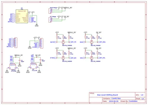
With that out of the way let’s look at the schematic. You can see it matches the general form of the above circuit. I’ve added some capacitors, headers for the jumper, and the Grove ports themselves. It’s a fairly simple setup. The jumper is setup as the HV value for each of the signal lines allowing customization for both ports.
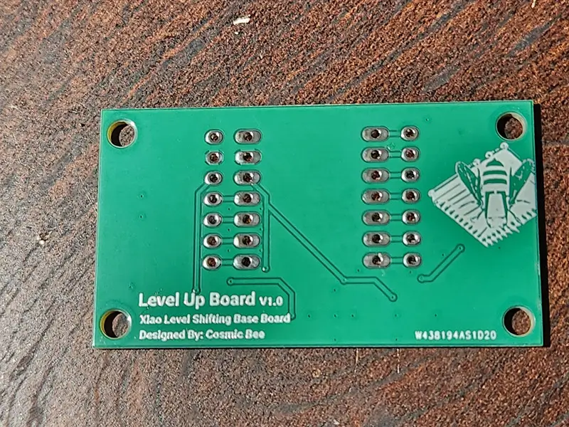
The PCB itself has no components on the backside.
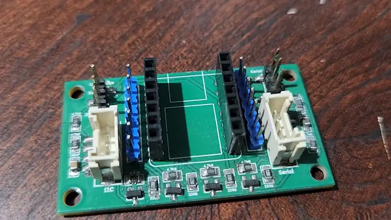
Assembly
Generally though the PCB has a silkscreen marking for each component listing the uF or ohms needed so I didn’t refer to the schematic while assembling. You should assemble the board with whatever you’re comfortable with if copying my steps here whether that’s individually soldering the components or using paste and hot air like I did.
Testing
You can refer to the video for more information but I preformed the following two tests prior to using the circuit.
- Continuity testing the various component points (confirming the pins from the Grove connector properly were soldered and checking for shorts)
- Using a test with all 4 signal pins set to
HIGHallowing me to use my multimeter to check the voltage levels
Test Code
Initial Test Circuit
void setup() {
  pinMode(D4, OUTPUT);
  pinMode(D5, OUTPUT);
  pinMode(D6, OUTPUT);
  pinMode(D7, OUTPUT);

  digitalWrite(D4, HIGH);
  digitalWrite(D5, HIGH);
  digitalWrite(D6, HIGH);
  digitalWrite(D7, HIGH);
}

void loop() {
}
This circuit is the one I used for testing. The goal here was to simply set each of the various pins to a HIGH state such that I could test them once shifter.
Water Atomization Circuit
Additional Project items (affiliate links):
Code:
void setup() {
  pinMode(D7, OUTPUT);
  digitalWrite(D7, HIGH);
}

void loop() {
}
For this example I simply set the RX pin (D7) to HIGH such that the enable pin is activated and the logic can run. There’s nothing special about this set of code it just keeps the EN pin HIGH allowing it to function. When Grove modules only use with pin they use the outer pin and have the inner signal pin set to a not connected (NC) state.
i2c Test Circuit
The i2c test circuit used here is a built in example for SSCMA for inferencing over i2c.
Additional Project items (affiliate links):
Code:
#include <Seeed_Arduino_SSCMA.h>

SSCMA AI;

void setup()
{
    AI.begin();
    Serial.begin(9600);
}

void loop()
{
    if (!AI.invoke())
    {
        Serial.println("invoke success");
        Serial.print("perf: prepocess=");
        Serial.print(AI.perf().prepocess);
        Serial.print(", inference=");
        Serial.print(AI.perf().inference);
        Serial.print(", postpocess=");
        Serial.println(AI.perf().postprocess);

        for (int i = 0; i < AI.boxes().size(); i++)
        {
            Serial.print("Box[");
            Serial.print(i);
            Serial.print("] target=");
            Serial.print(AI.boxes()[i].target);
            Serial.print(", score=");
            Serial.print(AI.boxes()[i].score);
            Serial.print(", x=");
            Serial.print(AI.boxes()[i].x);
            Serial.print(", y=");
            Serial.print(AI.boxes()[i].y);
            Serial.print(", w=");
            Serial.print(AI.boxes()[i].w);
            Serial.print(", h=");
            Serial.println(AI.boxes()[i].h);
        }
        for (int i = 0; i < AI.classes().size(); i++)
        {
            Serial.print("Class[");
            Serial.print(i);
            Serial.print("] target=");
            Serial.print(AI.classes()[i].target);
            Serial.print(", score=");
            Serial.println(AI.classes()[i].score);
        }
        for (int i = 0; i < AI.points().size(); i++)
        {
            Serial.print("Point[");
            Serial.print(i);
            Serial.print("]: target=");
            Serial.print(AI.points()[i].target);
            Serial.print(", score=");
            Serial.print(AI.points()[i].score);
            Serial.print(", x=");
            Serial.print(AI.points()[i].x);
            Serial.print(", y=");
            Serial.println(AI.points()[i].y);
        }
        for (int i = 0; i < AI.keypoints().size(); i++)
        {
            Serial.print("keypoint[");
            Serial.print(i);
            Serial.print("] target=");
            Serial.print(AI.keypoints()[i].box.target);
            Serial.print(", score=");
            Serial.print(AI.keypoints()[i].box.score);
            Serial.print(", box:[x=");
            Serial.print(AI.keypoints()[i].box.x);
            Serial.print(", y=");
            Serial.print(AI.keypoints()[i].box.y);
            Serial.print(", w=");
            Serial.print(AI.keypoints()[i].box.w);
            Serial.print(", h=");
            Serial.print(AI.keypoints()[i].box.h);
            Serial.print("], points:[");
            for (int j = 0; j < AI.keypoints()[i].points.size(); j++)
            {
                Serial.print("[");
                Serial.print(AI.keypoints()[i].points[j].x);
                Serial.print(",");
                Serial.print(AI.keypoints()[i].points[j].y);
                Serial.print("],");
            }
            Serial.println("]");
        }
    }
}
I didn’t change anything with this circuit just reused the existing one to demonstrate the level shifting here.
Serial Test Circuit
For this example project I setup a serial test circuit by utilizing an Arduino Uno, Base Shield V2, a Grove Buzzer, a Grove buzzer, and my Level Up board.
Given the Uno board only allows for one serial connection I opted for Software Serial utilizing the NeoSWSerial library with a slower baud rate.
When the button on the Xiao side (with my level up board) is pressed it sends a message across the serial connection. On the Uno side the logic listens for commands and when it receives the associated message it triggers the buzzer.
Additional Project items (affiliate links):
- Grove Button
- Grove Buzzer
- Grove Base Shield V2
- Arduino Uno Rev3 - although I suggest the Uno Rev4 board
Arduino Uno
#include <NeoSWSerial.h>

// Define the software serial pins
const int rxPin = 6; // RX pin
const int txPin = 5; // TX pin

NeoSWSerial mySerial(rxPin, txPin);

const int buzzerPin = A0;
const String triggerMessage = "BUZZER_ON";

void setup() {
  pinMode(buzzerPin, OUTPUT);
  digitalWrite(buzzerPin, LOW);

  mySerial.begin(9600);
}

void loop() {
  if (mySerial.available() > 0) {

    String message = mySerial.readStringUntil('\n');
    message.trim();
    if (message == triggerMessage) {
      digitalWrite(buzzerPin, HIGH);
      delay(1000);
      digitalWrite(buzzerPin, LOW);
    }
  }
}
The Uno logic here is fairly simple it sets up the buzzer as an output on the A0 pin (the same pin that has the buzzer connected over a Grove cable), it sets up a serial connection using the pins D5 and D6, and then during the loop it looks for newlines indicating a received message, compares it to the trigger for the buzzer, and if found turns it on for a second.
Xiao ESP32S3
const int buttonPin = D5;
const String triggerMessage = "BUZZER_ON";
bool buttonState = LOW;
bool lastButtonState = LOW;
HardwareSerial SerialOut(0);

void setup() {
  pinMode(buttonPin, INPUT);
  SerialOut.begin(9600, SERIAL_8N1, -1, -1);
}

void loop() {
  buttonState = digitalRead(buttonPin);

  if (buttonState == HIGH && lastButtonState == LOW) {
    SerialOut.println(triggerMessage);
  }

  lastButtonState = buttonState;
  delay(50);
}
On the Xiao side the code is fairly simple. It sets up D5 as a button (here I’m using the i2c pins for the button), it then starts a hardware serial connection using the lower baud rate we set for the Uno, and it then just listens for button events and triggers the message based on that.
Closing Thoughts
This board works great for its intended purpose. It wasn’t hard to put together as it uses just a few components, its compact so it can be used with various projects, and it level shifts well.
I’ll be using the Seeed Grove Vision AI Module V2 for more projects in the future so this board will come in handy for those. I have a few more projects on the way in the future so will have more articles once those are ready!